


- Topology Optimization of a Lightweight Multi-material Cowl Cross Member Using Matrix Input with the Craig Bampton Nodal Method
Dong il Son*, Sangwoo So**, Dong hyuk Choi*, Daeil Kim***†
* R&D Center, Dongkook Ind. Co., Ulsan
** Automotive Parts Institute & Center, Ulsan Technopark
As demand of light weight in the automotive industry
has increased, the cowl cross member has been investigated using various
methods to change the material. Conventionally, a cowl cross member has been
made of steel and aluminum, but recently researchers tested multi-material such
as aluminum and plastic. We studied a new model of the cowl cross member made
of composite and non ferrous materials. For products with a high degree of
freedom in design, generally, the method of topology optimization is
advantageous and for the partial bracket part of the cowl cross member had a
degree of freedom in the design, a topology optimization is appropriate.
Considering the characteristics of the cowl cross members, we need research to
minimize the weight while having the performance of noise, vibration and
harshness(NVH). Taking the mounting status of the product into consideration,
we used an assembly model to optimize the cowl cross member. But this method
took too much time so we considered simple cowl cross member assemble
conditions using the direct matrix input method(DMI) with the Craig-Bampton
Nodal Method. This method is capable of considering the status of the assembly
without assembling the model, which reduced the solving time and increased the
accuracy comparison with a cowl cross member without DMI.
Keywords: : DMI (Direct matrix input), Craig-Bampton nodal method, Topology optimization, Super-element, NVH (Noise, vibration and harshness), Multi-material
Recently,
the automotive industry has been going toward xEV (BEV, HEV, PHEV, FCEV) and
smartification so the curb weight has been increased by additional parts such
as batteries, motors, and electric parts. Light weight is a very important
factor in developing automotive parts in the automotive industry. A cowl cross
member is made of many parts, and each serves a special purpose in the
structure [1]. The cowl cross
member(CCM) supports the instrument panel (IP) system and the relevant NVH performance.
For several decades, many car makers have been developing various CCMs to
achieve light weight and satisfactory NVH performance. For sake of light
weight, the material of the CCM has been changed from steel to aluminum,
magnesium and a hybrid material made of steel and engineering plastics. In this
study, we propose a hybrid material CCM made of magnesium, aluminum, and
polyamide6-glass fiber to achieve light weight and NVH performance.
In
particular, nylon6-glass fiber composite materials have relatively strong
thermal and shock characteristics among polymeric materials, which are
applicable to automotive parts that are currently undergoing changes to plastic
materials, which are increasing [2,3].
The
CCM is a main component of the car body frame and contributes to the overall
integrity and stiffness that affects the frequency response of the entire
vehicle. The CCM is the part that transfers the load from the steering column
to the body through its junctions with the car body on the sides, top and
bottom. Both ends of the CCM meet the A-Pillar on the side, and the middle end
point meets the Center floor [4]. The brackets of the fixed points to the A-Pillar and the
Center floor can be made of composite materials and magnesium materials that
does not consider the direction of flow, so it can have a high degree of
freedom in design due to manufacturing the injection molding for engineering
plastics and die casting for magnesium. In this case, the design of the bracket
is suitable for topology optimization because topology optimization has been
primarily applied for the preliminary design of solid structures, and
mechanical parts had a high degree of freedom in the design [5].
In
terms of the role of the CCM, we have to consider the performance of NVH
transmitted from the automotive body, so the CCM must consider the assembly
conditions. In the topology optimized process, much time was spent to solve the
assembly model, the so-called full model. For this reason, we investigated the
DMI method with the Craig-Bampton Nodal Method which could consider the
assembly conditions without an assembly model. In this case, we defined the
super-element of the CCM which meets the A-Pillar on the side and the center
floor on the middle. Using the super-element, we accepted the effect of the assembly
conditions to use only the CCM component. The super-element defines as an
external node connected rigid body that facilitates sharing models between the
design group and the non-design group [6,7] and expresses the
performance of NVH transmitted by the non-design group through the reduced
matrices that accomplishes a topology optimization.
There
are two approaches in a topology optimization method: the density method [8] and homogenization
methods [9].
In
this paper, first, we suggest a reduced model of CCM assembly with the
Craig-Bampton procedure based on free interface modes and where the
substructures are assembled through the interface force. Second, we suggest the
optimized CCM model using the topology optimization method with the density method.
2.1
Craig-Bampton nodal method
The
Craig-Bampton method is especially well suited for a sub-structuring problem [6]. In the course of
a finite element solution, the matrix representation of a structure’s
stiffness, mass, damping, and loading are generated. The system equations using
these matrices are solved to simulate the structures’ behavior. The time taken
for these matrix solutions is generally proportional to the square of the
number of degrees of freedom of the structure [10]. To save
simulation time, the non-design portion of the structure is removed and the
design portion of the structure is retained using the super-element by the
method of reduced matrices.
The
Craig-Bampton reduction basis consists of a combination of static condensation
modes and eigenmode of the fixed, undamped structure [11].
The
following is common to all super-element generation methods and the details of
the initial partitioning step involved in generating the reduced matrices.
The
linear static equations can be expressed by:
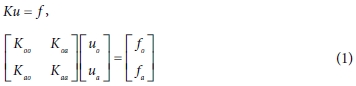
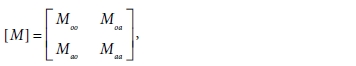
Here,
the subscript o denotes the inner degree of freedom, and the a denotes the degree of freedom of the
interface.
K is the stiffness matrix and u and f are the displacement
and force vectors.
The
two resulting equations yield:

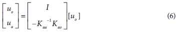
This
equation can be expressed as follows:

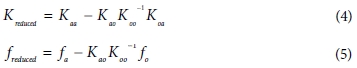
So
the reduced stiffness and the reduced loading are:
A
coordinate transformation u = Tuo
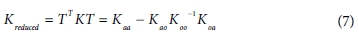
The
reduced stiffness matrix can be written by:
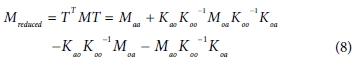
Then
with
the reduced mass matrix becomes:
An
eigenvalue analysis is performed on the reduced matrices as follows:

where λ is an eigenvalue
and A is the partitioned eigenvectors of the system.
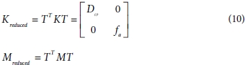
A
normal modes analysis of the fixed-interface system yields the diagonal matrix
of eigenvalues Dω and the matrix of
eigenmodes Aω . The column dimension of Aω can select the cut-off frequency or the number of
modes. The static displacement modes are the matrix As and the interface
forces fa.
In
this field, T is written as T = [Aω As].
The
reduced stiffness matrix and mass matrix are
2.2
Topology optimization
The
object of optimization is to accelerate the design process and to increase the
efficiency of the final design, thus providing maximum performance using
minimal materials. Thus for the design of a new product, the method of topology
optimization is the most effective based on the material distribution method
and the calculated optimized size by modifying the stiffness matrix to depend
on material density that is allowed to vary continuously between a solid and a
void [5,12].
In
this study, we used the material distribution to complete the optimization
under given constraints, which is gradient-based optimization method.
First,
to avoid resonance in a structure and to meet the NVH requirement, it is
important that the optimal topology be within the proper range of the
structure’s natural frequency [13]. The natural frequencies of the CCM must be different due
to different boundary situations generated by attached structures.
In
general, when a vehicle is operating, the resonance value can be determined by
the engine’s vibration and structure of the power train [1]. Hence, the car makers
suggest the value of natural frequency that is over 38 Hz at the first mode.
The
optimization problems statement of the CCM is
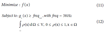
where f(x) is
the mass function and g(x) is the frequency function and ρ(x) is the
density function, Ω is volume and W is a design domain.
3.1
Topology optimization of CCM with DMI
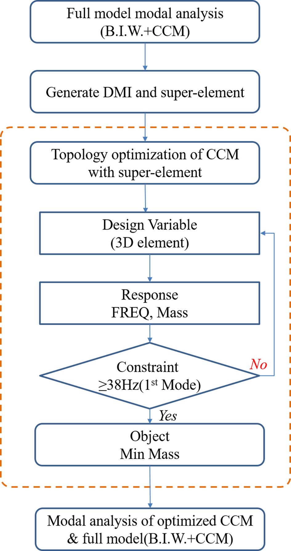
For
the sake of topology optimization of the CCM, we used the direct method
input(DMI), which is a reduced model. The process of the simulation is 1) we
accomplish the modal analysis of the full model, 2) we generate the DMI model
using the reduced model, 3) we optimize the CCM with the super-element
considering the boundary of the full model and lastly, we analyze the modal
analysis of the full model including the optimized CCM.
In
this optimization process, the objective and the constraint functions are as
follows;

The
process of simulation is shown in Fig. 1. The analysis of the simulation uses the commercial
software OptistructTM. In the case of full model with the CCM
concept model, the first mode frequency is 45.1 Hz and the second mode
frequency is 47.4 Hz.
As
shown in Fig.
2, the super-element is at the location of hard point and the
super-element is the part of the CCM that is connected by a rigid body and the
B.I.W. corresponding to the target CCM and the boundary condition.
Fig.
3 shows the full model considering the mounting status of the CCM in
B.I.W.
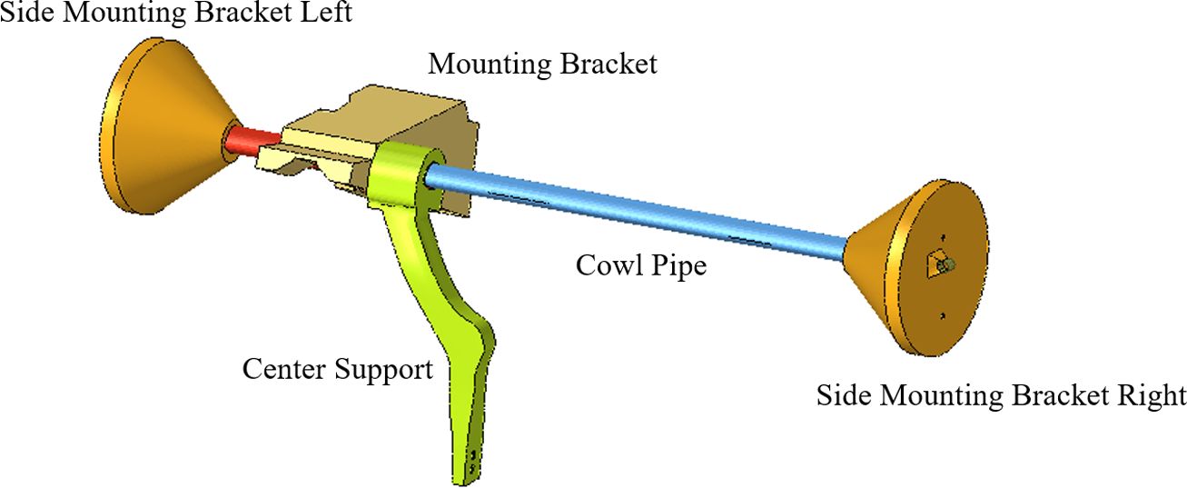
The
component models to optimize are the mounting bracket, the side mounting
bracket, and the center support as expressed by Fig. 4.
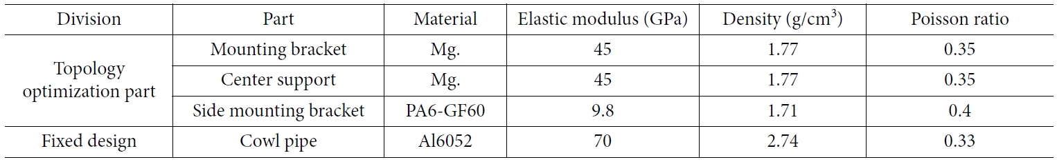
The
materials of components are magnesium and composite (PA6-GF60: 60% long strand
glass fiber reinforced nylon 6 Natural) and the cowl pipe as a non-design part
is made of aluminum. Table
1 shows the materials and properties applied to each part as shown Fig. 4.
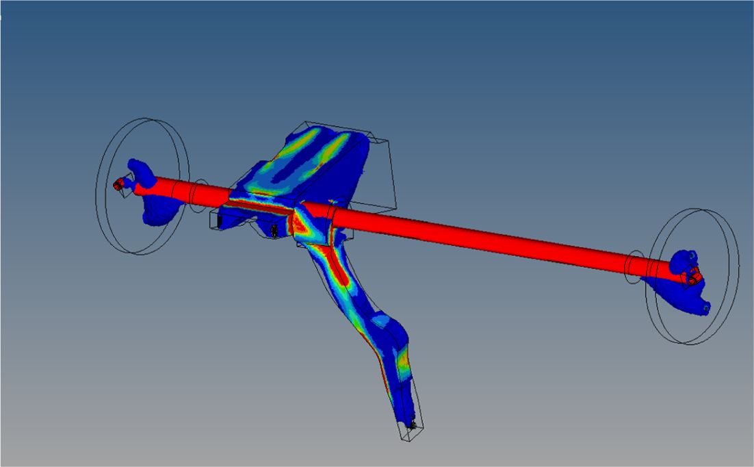
We
use the topology optimized conditions to minimize the mass and to raise the
value to 38 Hz; the design is illustrated by Fig. 5. The target
components were optimally designed only for parts that significantly affect a
NVH performance. The rest of the parts refer to the existing cowl cross member
geometry.
In
addition, we designed the new model as in Fig. 6 based on the
topology optimized model of the CCM to consider manufacturing conditions such
as the plastic injection process and magnesium die casting process.
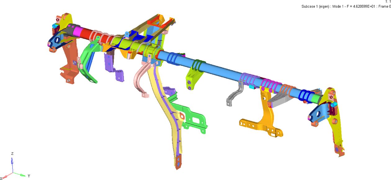
In
the NVH performance of the optimized model the first natural frequency is 38.37
Hz and second natural frequency is 39.58 Hz and the weight is 5.148 kg. Based
on the first natural frequency value, the result of the NVH performance of both
the full model and only the CCM using the super-element are 38.33 Hz and 38.37
Hz, respectively. Fig.
7 shows the primary natural frequency and mode shape with super-element and
full model. There is little difference in results. On the other hand, the
number of nodes of the CCM model and the full model including the CCM are
62,713 nodes and 790,202 nodes, respectively. The size of model for NVH
performance analysis considering BIW mounting conditions has been reduced to
1/12. Moreover, the solving time is 39 times faster on the basis of 4 CPUs of
2.60 GHz. Table
2 shows the size and analysis time of full and the reduced models.
|
Fig. 1 The process of topology optimization of the CCM using DMI |

|
Fig. 2 Super-element assignment (The red circle denote superelement) |

|
Fig. 3 Full model included the concept model of the CCM |
|
Fig. 4 The concept model of the CCM |
|
Fig. 5 The topology optimized model of the CCM |
|
Fig. 6 The optimized model of the CCM |

|
Fig. 7 1st and 2nd natural frequency of the CCM using the superelement and full model |

4.1
Modal test of the CCM
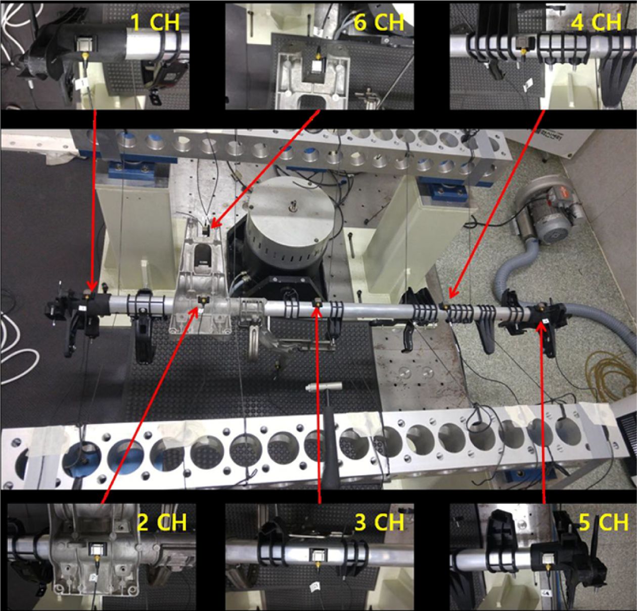
Based
on the optimized design as shown in Fig. 6, we made the CCM
as in Fig. 8 and estimated the natural frequency as in Fig. 9 which is a
non-constraint; in other words, the boundary conditions are free-free
conditions and measure 6 points. The condition of the vibration input is that
the brittle point of the CCM is impacted by the impact hammer (B&K
8206-002) in the vertical direction and uses the 3-axis acceleration sensor
(B&K 4506B).
The
result of the test was as follows: the first natural frequency is 40.8 Hz and
the second natural frequency is 43.7 Hz as shown Fig. 10 and Fig. 11.
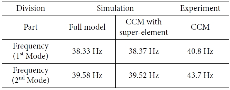
Table
3 summarizes the results of the simulation and experiments. In the result
of experiment and simulation, the difference of the frequency value was less
than 2.5 Hz and the percentage was about 6%. Although we expected that an error
might occur from the experiment and manufacturing, the result of the simulation
can be considered as reliable. Comparing other CCMs made of steel material of a
similar vehicle model with the hybrid material CCM in this study, the weight of
the steel type and hybrid type are 8.7 kg and 4.79 kg, respectively.

|
Fig. 8 The product of the CCM |
|
Fig. 9 Experimental set up of the CCM for estimating natural frequency |

|
Fig. 10 Frequency response graph at Z direction(vertical) –40.8 Hz |

|
Fig. 11 Frequency response graph at X direction (longitudinal)– 43.7 Hz |
In
this study, we achieved two outcome as follows:
Firstly,
the model size of the CCM for the finite element analysis decrease 1/12; in
other words, the matrices of model decreased 91% with the same accuracy in
terms of full model frequency.
Secondly,
sub-models considering the mount of assembly model without assembly model were
presented and have the accuracy over 93% compare to experiment. It means if the
design of CCM change other type, it is not necessary the full model composed
B.I.W. and CCM.
Thirdly,
through the hybrid material made by magnesium, aluminum, and engineering
plastics, the CCM achieved a reduced weight by 44.9% compared to the
conventional CCM.
- 1. Lam, K.P., Behdinan, K., and Cleghorn, W.L., “A Material and Gauge Thickness Sensitivity Analysis on the NVH and Crashworthiness of Automotive Instrument Panel Support”, Thin-walled Structures, Vol. 41, No. 11, 2003, pp. 1005-1018.
-

- 2. Shao, M.W., Huang, J.J., Chen, Y.X., and Hwang, S.S., “Synthesis and Characterization of the Microcellular Injection Molded PA6/flax and the PA6/graphene Nanocomposites”, in IOP Conference Series: Materials Science and Engineering, 2019. IOP Publishing.
-
- 3. Lee, B.Y., and Kim, Y.C., “Study on the Physical Properties of Nylon66/glass Fiber Composites as a Function of Extrusion Number”, Journal of the Korea Academia-Industrial Cooperation Society, Vol. 15. No. 6, 2014, pp. 3990-3996.
-
- 4. Rahmani, M., Multidisciplinary Design Optimization of Automotive Aluminum Cross-car Beam Assembly, 2013.
- 5. Kim, C., and Sun, H., “Topology Optimization of Gas Flow Channel Routes in an Automotive Fuel Cell”, International Journal of Automotive Technology, Vol. 13, No. 5, 2012, pp. 783-789.
-
- 6. Craig, J.R., “Coupling of Substructures for Dynamic Analyses-an Overview”, in 41st Structures, Structural Dynamics, and Materials Conference and Exhibit, 2000.
-
- 7. Rixen, D.J., “A Dual Craig-bampton Method for Dynamic Substructuring”, Journal of Computational and Applied Mathematics, Vol. 168, No. 1-2, 2004, pp. 383-391.
-
- 8. Rozvany, G.I., Zhou, M., and Birker, T., “Generalized Shape Optimization without Homogenization”, Structural Optimization, Vol. 4, No. 3-4, 1992, pp. 250-252.
-
- 9. Bendsøe, M.P., and Kikuchi, N., “Generating Optimal Topologies in Structural Design Using a Homogenization Method”, Computer Methods in Applied Mechanics and Engineering, Vol. 71, No. 2, 1988, pp. 197-224.
-
- 10. Hyperworks, Hyperworks Solvers Theory, 2017.
- 11. Holzwarth, P., and Eberhard, P., “Interface Reduction for CMS Methods and Alternative Model order Reduction”, IFAC-Papers on Line, Vol. 48, No. 1, 2015, pp. 254-259.
-
- 12. Gebisa, A.W., and Lemu, H.G., “A Case Study on Topology Optimized Design for Additive Manufacturing”, in Materials Science and Engineering Conference Series, 2017.
-
- 13. Cho, K.H., Park, J.Y., Ryu, S.P., Park, J.Y., and Han, S.Y., “Reliability-based Topology Optimization Based on Bidirectional Evolutionary Structural Optimization Using Multi-objective Sensitivity Numbers”, International Journal of Automotive Technology, Vol. 12, No. 6, 2011, pp. 849-856.
 This Article
-
2019; 32(5): 243-248
Published on Oct 31, 2019
- 10.7234/composres.2019.32.5.243
- Received on Jul 19, 2019
- Revised on Sep 17, 2019
- Accepted on Sep 23, 2019
Services
Shared
Correspondence to
- Daeil Kim
-
School of Material Science & Engineering, University of Ulsan
- E-mail: dkim84@ulsan.ac.kr
Gangnam Mirae Tower, Suite 601, 174 Saimdang-ro, Seocho-gu, Seoul 06627, South Korea
Tel: +82-2-598-1550 Fax: +82-2-598-1557 E-mail: composites@kscm.re.kr