


- Test and Analysis of Triaxially Braided Composite Circular Arch under Three-Point Bending
Biruk F. Nega*, Kyeongsik Woo**†, Hansol Lee***
* Dept. of Civil Systems Engineering, Chungbuk National University
**† School of Civil Engineering, Chungbuk National University
In this paper, the buckling behavior of triaxially
braided circular arch with monosymmetric open section subjected to three-point
bending was studied experimentally and numerically. First, test specimens were
manufactured using vacuum assisted resin transfer molding (VARTM). Then the
specimen was tested under three-point bending to determine the ultimate
buckling strength. Before performing the numerical analysis, effective material
properties of the braided composite were obtained through micro-meso scale
analysis virtual testing validated with available test results. Then linear
buckling analysis and geometrically non-linear post buckling analysis,
established to simulate the test setup, were performed to study the buckling
behavior of the composite frame. Analysis results were compared with
experimentally obtained ones for verification. The effect of manufacturing
defects of tow misalignment, irregular surface and resin rich region, and
uncertainties during test setup were studied using numerical models. From the
numerical analyses performed it was observed that both manufacturing defect and
uncertainties had effect on the buckling behavior and strength.
Keywords: Triaxial braid, Composite arch frame, Buckling, Manufacturing defect
In
recent years advanced composite materials are being extensively used as primary
structures in aerospace, military and automotive industries. They are favored
for their high strength to weight ratio, corrosion resistance, requirement in
material anisotropy and the advantage that their properties can be tailored to
yield specific requirements. As laminated composite materials have been used in
layered stacking the propensity to delamination due to out-of-plane loading was
high [1] which is due to
relatively poor resin strength which held the fibers together. Hence braided
textile composites which are manufactured by interweaving tows running in
different direction were developed to lessen delamination due to out-of-plane
loading. Braided textile composites are favored over pre-preg laminates for
their better out-of-plane properties, near net shape fabrication, impact and delamination
resistance and overall high performance [2]. They are widely used in various application areas including
thin walled composite structures.
Thin
walled composite structures are commonly used in aerospace industries due to
sufficient in-plane performance at the same time reducing the overall
structural weight [3]. One area where
thin walled composites are employed is arched frames. Composite arched frames
offer combined advantage of high strength-to-weight ratio and efficient load
transferring mechanism through both axial compression in the hoop direction and
bending action which make them suit for many applications. The distinguishing
characteristic of arches from beams is that the presence of end reaction force
as they transfer the loading into axial compression in addition to the
considerable rise of the axis at the center. For beams supporting transverse
loading the bending moment increases as the length and become uneconomical for
longer span structures or structural members, hence arched structures are
favored for such applications.
Consequently,
arched structures offer advantage as they develop horizontal reaction force
which reduces the design bending moment [4]. And on the contrary, the
component of the end reaction in arched beams will also be the cause of
buckling and the structure may fail due to torsional buckling. Hence the
performance of arched structure to flexural torsional buckling depend on the
combination of in-plane and out-of-plane deflections, rotations, and twist and
warping of the cross section [5]. The buckling resistance of arched structures in general
depends on factors such as slenderness, rise-to-span ratios, out-of-plane
bending and torsional rigidities, arch-end restraints and initial geometric
imperfections. Moreover, circular frames having open cross section, i.e.,
monosymmetric cross sections such as C channels, are subjected to severe
instability issue. This is due to the development of additional torsional and
twisting behavior as the shear center do not coincide with center of gravity of
the cross section.
Previous
studies to investigate the lateral torsional buckling of arched structures were
mainly focused on steel sections. For instance, Guo et al. [6] studied the
out-of-plane inelastic buckling strength of steel arches under symmetric and
non-symmetric loading conditions using experimental test and finite element
method. From their study they found out that the inelastic buckling strength of
fixed arch steel structures is influenced significantly by the magnitude and
distribution of initial out-of-plane geometric imperfection. Another study by
Dou et al. [5] investigated the
flexural-torsional ultimate resistance of steel arches under symmetric and
unsymmetrical loading using experimental test and finite element techniques.
Following the development of industries in using advanced composite materials
for thin walled structures, studies are being performed on lateral torsional
behavior of composite members too.
For
instance, Barbero and Tomblin [7] investigated global buckling and determined critical
buckling load of fiber reinforced composite I-beam using experimental tests and
compared with theoretical predictions. Davalos et al. [8] also performed combined
analytical and experimental study on the flexural torsional buckling of
pultruded FRP composite. Another study conducted by Omidvar and Ghorbanpoor [9] developed non-linear
finite element (NLFE) analysis based on lagrangian formulation for the analysis
of thin-walled open section composite structural member.
In
the current study buckling behavior of triaxially braided composite arch frame
was studied using both experimental test and finite element analysis. Elastic
mechanical properties were first obtained using micro-meso multi-scale finite
element analysis from constituent material properties and measured braid
geometric dimensions. Then linear buckling analysis and geometrically
non-linear post buckling analysis were performed to study the buckling behavior
and subsequently determine the ultimate buckling load. Finally, the effect of
defects and uncertainties were studied using numerical model.
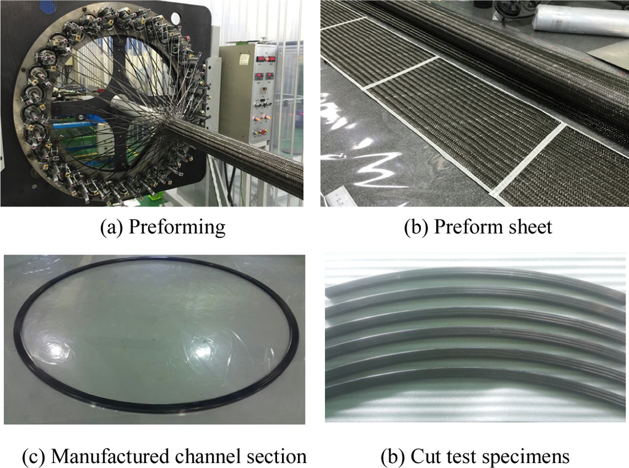
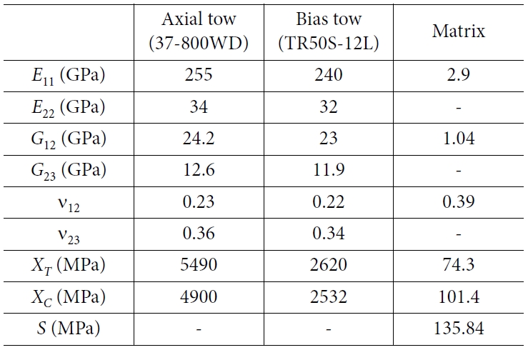
For
the current study, the test specimens were manufactured from high performance
carbon fibers impregnated with epoxy matrix. The axial tow is made from
37-800WD 30K high performance carbon (made by Mitsubishi Rayon Carbon Fiber
& Composites, Inc.) and the bias tow from TR50S-12 fiber (made by Grafil
Inc.). Fig.
1 shows the specimen preparation. First, triaxial braid preform sheets were
fabricated, which were then stacked and molded with rigid steel blocks using
VaRTM (Vacuum Assisted Resin Transfer Molding) composite manufacturing process
which uses vacuum assisted resin transfer into braided fiber lay-ups. After
impregnation the composite frame was allowed to cure at specified temperature.
The braiding angle and the fiber volume fraction of (fvT)
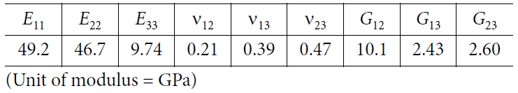
were measured to be 66o and 47%, respectively. The constituent fiber
and matrix properties are given in Table 1.
The
finished product was manufactured with the required outer cross-sectional
dimensions and diameter with an average thickness of 2.57 mm. The circular
frame which had a diameter D = 2569.4 mm was then cut in to test sample
dimension with 1/6 (60o) circular axis as shown in Fig. 1(d). The detail
cross-sectional dimension of the test specimen is given in the next section.
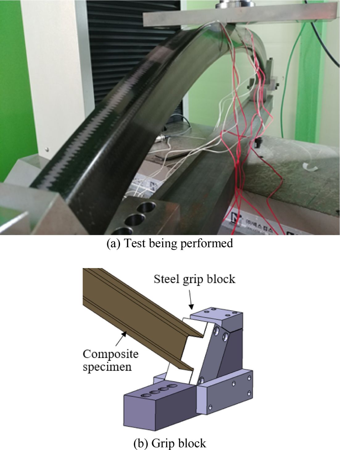
Fig.
2 shows the test being performed, where the two ends of the composite
frame were constrained by a steel grip block system. One of the two grip blocks
is shown Fig.
2(b) which is assembled to the bottom steel bar by bolts. The
vertical loading was applied at the crown via a thick steel plate. The test was
performed using a universal testing machine (UTM) in accordance with standard
guideline [10] with
displacement-controlled loading. The speed of the applied displacement was
1 mm/min. The vertical loading and the corresponding specimen displacement
were measured from attached load cell and movement of the cross head,
respectively. Local strain responses were also read from strain gauges attached at different locations.
|
Fig. 1 Specimen preparation |
|
Fig. 2 Specimen under test |
3.1
Finite element modeling of circular arch
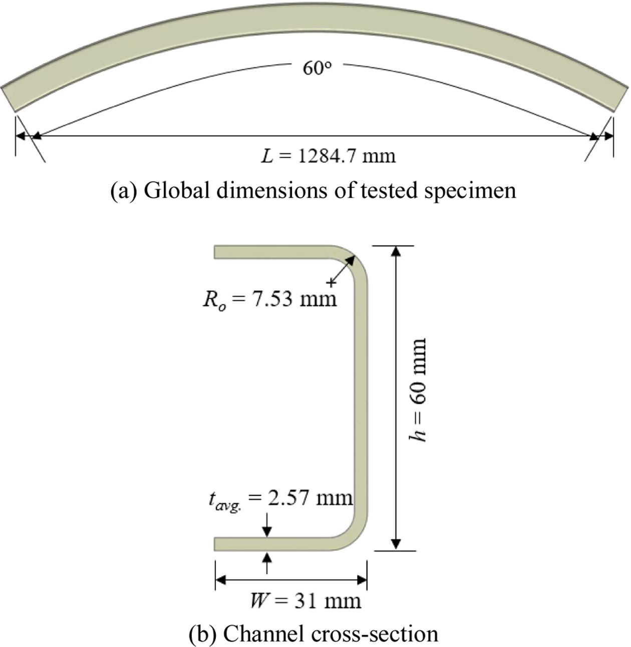
Fig.
3 shows analysis configuration with its global and cross-sectional
dimensions for pristine composite circular arch structure. The specimen had a
length of L = 1224.7 mm between inner support ends with cross sectional dimension of
height h = 60 mm, width W = 31 mm and outer curve radius Ro
= 7.53 mm.
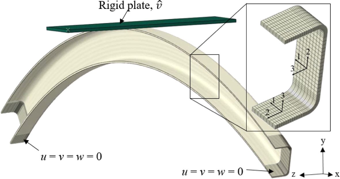
Fig.
4 shows the finite element model with its boundary conditions. For the
analysis of circular arch, commercial software ABAQUS was adopted to establish
finite element simulation model of the test process with geometrically
non-linear static analysis procedure. Even though shell and continuum shell
elements are commonly used in finite element modeling of thin walled
structures, 3D solid elements were used in the current study to consider
thickness-wise imperfections which will be discussed later.
After
preliminary mesh convergence study, the composite circular arch was modeled
using 135,408 eight node solid elements (C3D8) and 171,825 nodes for specimen
without manufacturing defect, and other configurations were also meshed with
the same or higher refinement. The element size was determined to explicitly model
the thickness variation occurred at the inner surface in the pattern of braided
fiber tows. It was also observed refined local mesh refinement on upper curved
section is important to ensure smooth contact transfer between the loading
plate and specimen during deformation. As in the actual test the loading was
introduced by means of flat plate; an analytically rigid plate was used with
displacement- controlled loading. Surface-to-surface contact having normal and
tangential properties was defined between the steel plate and composite
circular arch with 0.2 friction coefficient. Orthotropic material orientation
was assigned discretely where material direction 1 is in the axis of the arch,
2 in transverse direction and 3 in the out-of-plane direction at every point.
3.2
Buckling analysis
In
long and thin composite members subjected to compressive loading, buckling
failure occurs locally or globally before any other types of material or
instability failure [11]. Likewise, in long
composite members with non-symmetric cross-section there exist additional
coupled bending and torsion [12], hence, their flexural torsional buckling should be
considered.
The
buckling analysis using finite element analysis could be performed in two ways:
linear buckling analysis and non-linear post-buckling analysis. Linear buckling
analysis is commonly performed to obtain the theoretical buckling load and the
corresponding buckling mode shapes. But in actual structures, imperfections and
non-linearities resulting from material and geometry prevent from achieving the
theoretical elastic buckling strength. In contrast, non-linear post-buckling
analyses are performed to get detailed information on the progressive
deformation, strain and stress states and also on how the structure behaves
after initiation of buckling. To instigate buckling one may introduce initial
geometric imperfection to finite element mesh. The imperfection can obtained by
directly measuring the magnitude and distribution of the imperfection in
structure using ultrasonic scan [13], total station instrument [5] or other suitable mechanisms.
Other alternatives to instigate buckling are applying small perturbation load [14], introducing
random imperfection by disturbing nodal coordinates [15] or imperfection
based on preceding linear buckling analysis [16].
While
structures with symmetric geometry and loading condition require buckling
instigation techniques, buckling occurs without the instigation techniques for
mono-symmetric cross sections, as in the current study. This is due to the
non-coincident nature of shear center and centroid of open cross sections where
the reaction shear flow causes twisting which in turn instigates buckling.
Hence linear and geometrically nonlinear buckling analyses were performed
without such buckling instigation strategies. It was found from a preliminary
analysis that no material failure occurred because all stresses were lower than
the material strengths, and therefore failure modeling was not included.
3.3
Material properties
For
the triaxially braided textile composite used in this study, uniaxial tensile
tests in the material 1- and 2-directions were performed to obtain elastic
properties [17] according to
specific ASTM D3039 standard testing procedures [18]. For material
properties for which tests were not performed, micro-meso multi-scale finite
element analysis was performed using measured geometric braiding parameters.
First, micro-scale analyses were performed to obtain homogenized tow properties
from constituent material properties given in Table 1. For the
micro-scale analysis, commercial software MCQ/Composites [19] was used with the
fiber volume fraction in the tow (![]() ) of 84.3%. Next, the effective lamina
properties were obtained through meso-scale unit cell analyses simulating 3
uniaxial tension and 3 shear tests with the braiding angle of 66o and
the total fiber volume fraction (vfT) of 47%.
) of 84.3%. Next, the effective lamina
properties were obtained through meso-scale unit cell analyses simulating 3
uniaxial tension and 3 shear tests with the braiding angle of 66o and
the total fiber volume fraction (vfT) of 47%.
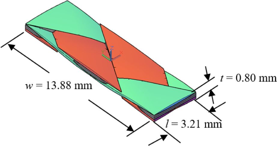
For
the meso-scale unit cell analysis, a repeating meso-scale unit cell model was
generated as shown in Fig. 5 from measured dimensions of the triaxially braided test
specimen. The geometry was generated assuming both axial and bias tow
cross-section to be lenticular and to run over straight and undulating path for
axial and bias tow, respectively. (Detail description of the modeling process
can be found in Ref. [20].) With the
generated finite element unit cell model, effective material properties were
obtained by performing a series of virtual tests simulating uniaxial and shear
tests in different directions. Table 2 summarizes the material properties obtained by tests and
numerical analyses. The predicted results agreed well to the test results [11] which validated
the numerical approach.
3.4
Defect identification
The
test specimen was examined and found to have a number of manufacturing defects.
These include tow misalignment, resin rich region, cross-sectional thickness
variation, and irregular cross-section. The effect of these defects was
investigated modeling them numerically.
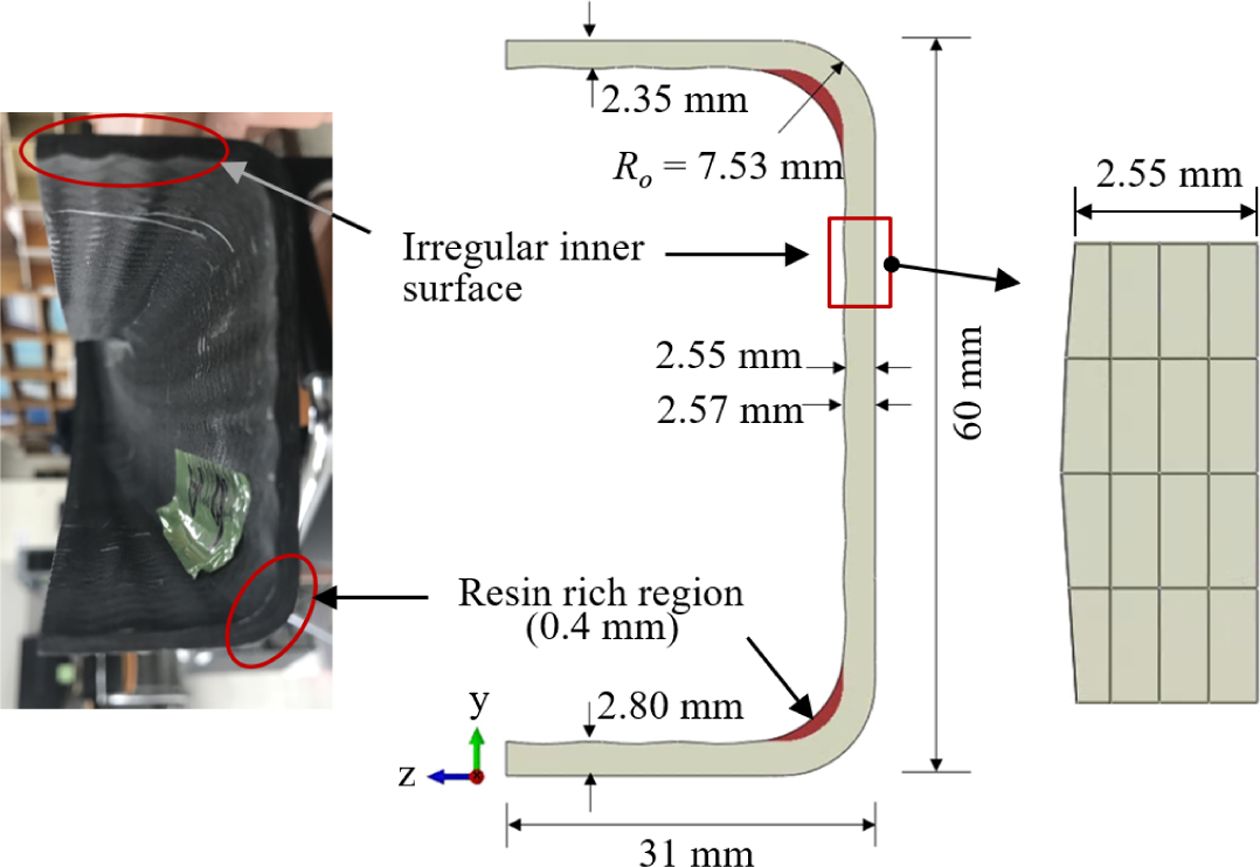
Fig.
6 shows the irregular inner surface and resin rich defects. Cross-sectional
dimensions measurements at different locations revealed different thickness
value at the web, upper flange and bottom flange. Stochastic distribution of
this variation was measured at 32 different locations at equal intervals which
showed the average thicknesses of 2.34 mm, 2.79 mm, and 2.56 mm for the upper
and lower flange, and for the web, respectively, with the standard deviation of
0.297. In addition to the average thickness variation, the manufacturing
process made the inner face (vacuum bag side) of the specimen wavy according to
the microstructural shape of axial and bias tows with 0.1 mm amplitude while
the outer surface (tool side) was flat. Also, during molding, as the braided
mat was laid on steel mold, the impregnated resin near the curve was squeezed
out to the re-entrant corner of the inner face. These defects of irregular
inner surface and resin rich region in the manufacturing process are taken into
account in the numerical modeling, see Fig. 6.
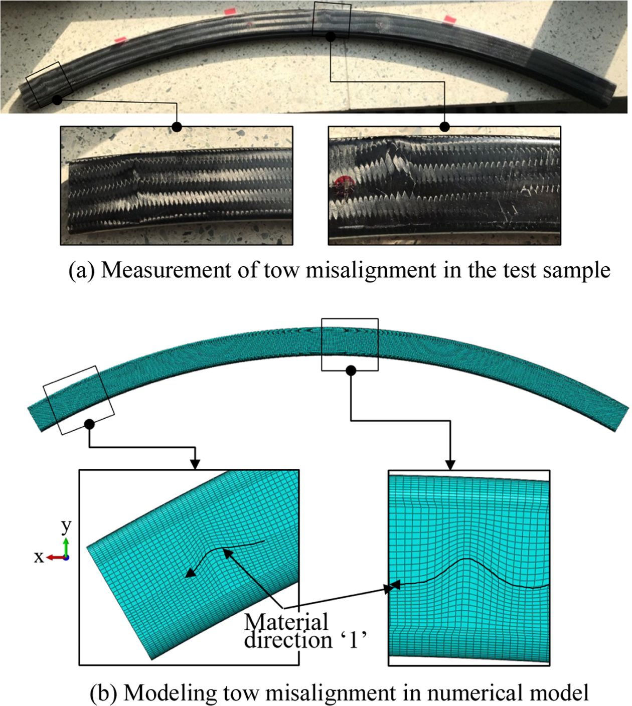
Similarly,
the tow misalignment was measured from the test specimen. The misalignment
occurred at 25 locations with the average off-set from the center line of 2.5o.
The misalignment was explicitly considered by first calculating the effective
properties for the misaligned part [17] and then by
arranging the mesh shape to follow the misaligned axial tow direction. In Fig. 7, the typical tow
misalignment and their corresponding finite element modeling are shown. The
material’s fiber direction was defined by connecting measured offsets at
different location with spline curve.
During
mounting the specimen for test, due to imperfect support grip and specimen
placement around 3o specimen tilting was measured from the span
center to the crown and vertical axis. This loading imperfection was taken into
account in the finite element modeling.
|
Fig. 3 Configuration of composite circular arch |
|
Fig. 4 FE modeling of composite arch |
|
Fig. 5 Meso-scale unit cell of triaxial braid composite |
|
Fig. 6 Defect of irregular inner surface and resin rich region |
|
Fig. 7 Measurement and modeling of tow misalignment |
4.1
Linear buckling analysis
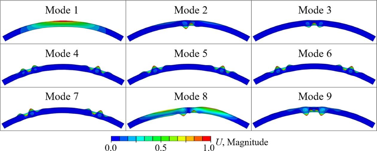
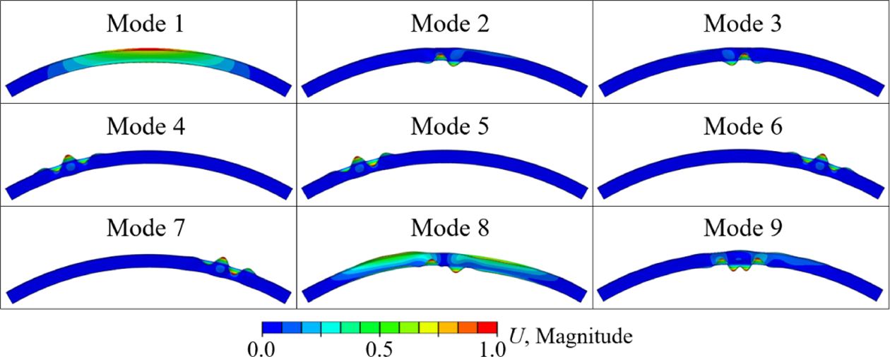
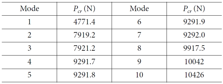
Fig.
8 and Table 3 show the first nine buckling mode shapes and the
first ten buckling loads, respectively, from linear eigenvalue analysis with
their corresponding scale factors. The analysis was performed by applying a
vertical load along the line at the upper surface which was the initial line
contact between the specimen and the loading plate throughout the analysis.
With regard to computational resource continuum shell can be more effective in
the analysis of thin-walled structures as fewer elements are used. However, the
continuum shell modeling has limitation in modeling of the present structure
because the characteristic thickness scale is not so small and the section
definition of the cross-sectional thickness variations as shown in Fig. 6 cannot be achieved.
Hence, 3D solid element modeling was used for all analyses.
As
can be seen from the figure, the first and the eighth buckling modes are the
global modes dominated by the out-of-plane global symmetric and anti-symmetric
deformations of the specimen respectively, while others are more of localized
deformation of bottom flange near the crown or top flange between the crown and
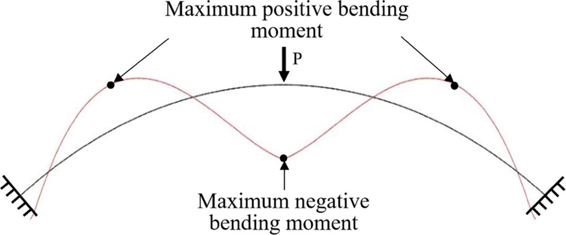
the support. On a typical simplified case where the concentrated load applied
at the crown of fixed circular arch with rectangular cross section, the maximum
bending moment appears at the crown and second pairs, symmetric, between the
crown and the support having opposite sign as shown in Fig. 9. Consequently, the
locations of local in-plane buckling are in agreement with these locations.
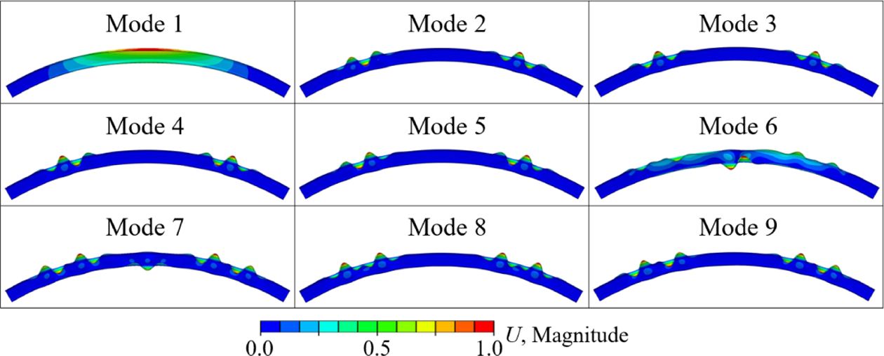
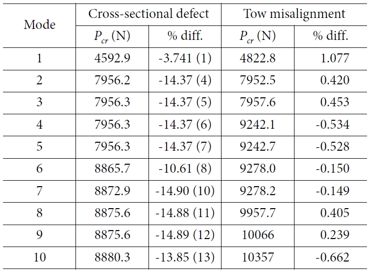
As
shown in Fig.
10 and
Table 4, the cross sectional defect affected the buckling mode
shapes and the buckling loads significantly. While the first mode shape and
buckling load agreed with small difference with those of the pristine model,
the modes 2-5 of the model with cross-sectional defect matched with the modes
4-6 of the pristine model and there occurred approximately 14% difference in
buckling loads. The sixth mode of the model with the cross sectional defect
seemed to match with the eighth mode of the pristine model, but the mode shape
was more complicated and the buckling load differed by 10.6% compared to that
of the pristine model. Similarly, the modes 7-10 with the cross sectional
defect corresponded to the modes 10-13 of the pristine model with approximately
15% differences.
For
the case of tow misalignment shown in Fig. 11, the effect was
found to be not so significant. The mode shapes of modes 1-3, 8 and 9 matched
with those of the pristine model and the difference in the buckling loads was
relatively small. For modes 4-7, the buckling deformation developed non-
symmetrically only at one side due to the non-symmetric occurrence of the local
tow misalignment defects, but the difference in the buckling loads was small.
From these results, one can see that the cross sectional defect had a larger
influence on the linear buckling behavior than the tow misalignment defect.
4.2
Geometrically nonlinear post-buckling analysis
In
the current configuration, even though buckling occurs naturally due to the
mono-symmetric cross section, preliminary imperfection sensitivity analysis was
also performed with geometrically non-linear post buckling analysis. For this
purpose, the lowest fundamental buckling mode from the linear buckling analysis
was selected, scaled, and applied to the mesh as initial geometric
imperfection. Imperfection magnitude ranges that are commonly used were
considered and found to have insignificant effect on both the elastic response
and the ultimate buckling load.
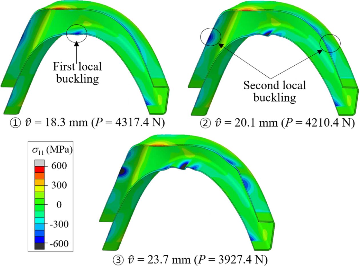
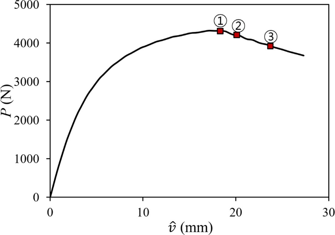
First,
a three-dimensional geometrically nonlinear analysis was performed for the
pristine model. A displacement controlled vertical load was applied by a flat
steel plate which transferred to the composite frame structure through contact
at the crown part of the frame. Fig. 12 shows the progressive deformation history at three
different loading stages marking the local buckling developments. The circled
numbers indicate the applied load state shown in the load-displacement curve of
Fig.
13. While the linear eigen analysis predicted the first global buckling
deformation mode to occur at Pcr = 4771.4 N, the non-linear
analysis showed the forward bending deformation to occur from the very
beginning which can also be seen form the highly non-linear load-displacement
curve.
As
the applied load was further increased to point (1), the deformation grows
which gave rise to the compressive stress at the bottom flange of the
mid-section part of the frame structure. This compressive stress instigated
local buckling there and it was this initiation of the local buckling which
determined the ultimate buckling load of 4317.4 N. The second and third
instability modes predicted from linear eigen analysis were anti-symmetric and
symmetric, respectively, at the bottom flange of the crown part, but the
nonlinear analysis showed symmetric deformation at the same location, i.e., the
second mode was skipped and the third mode developed. After that, the buckling
process proceeded quickly and the load-displacement curve started falling.
Then
at load point (2), while the local buckling deformation further developed and a
pair of local buckling started to appear at the upper flange between the crown
and the support. As the loading was further increased in the post-buckling
regime, point (3), previously instigated global and local buckling grew in size
and the load-displacement curve further decreased.
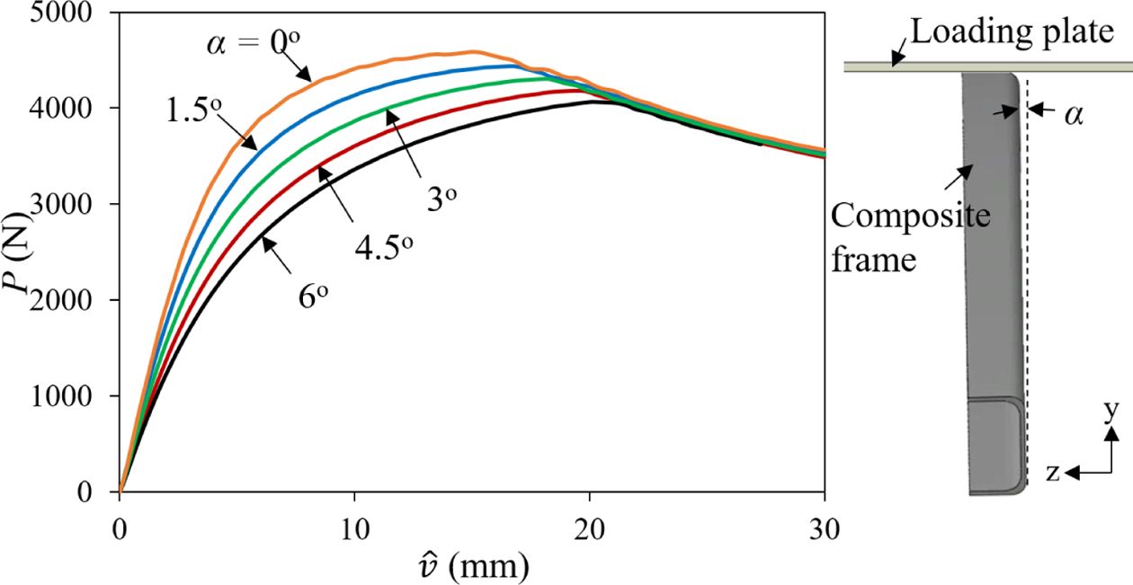
4.3
Effect of defects
From
examination of the test sample and test setup, various imperfections were
detected. These include cross sectional defect, local tow misalignment, and
specimen tilting. Out of these defects and uncertainties, the specimen tilting
had a considerable effect on predicted stiffness and ultimate buckling load.
Due to the nature of the test set-up, i.e., imperfect support grip and
uncertainties in the specimen set up for test 3o specimen tilting
was measured initially when full contact was developed between the loading
plate and the specimen. Parametric study for this tilting angle (α) was
performed and predicted load-displacement curves and its effect on ultimate
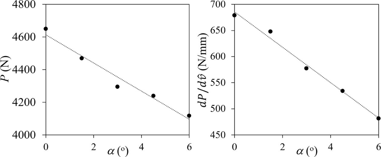
buckling load and specimen stiffness are presented in Figs. 14 and 15, respectively.
Specimen stiffness or the slope of the load-displacement curve was computed on
the initial linear response range. Analyses were performed for tilting angle
ranging from 0o to 6o with 1.5o increment.
From Fig.
15 it was observed that the ultimate buckling load and the initial
stiffness reduced by 11.4% and 29.1%, respectively, when α= 6o
compared to the pristine model with α = 0o. Even though it was
observed to have significant effect on both the stiffness and ultimate buckling
load, however, the post-buckled residual stiffness remained almost the
same when the tilting angle varied.
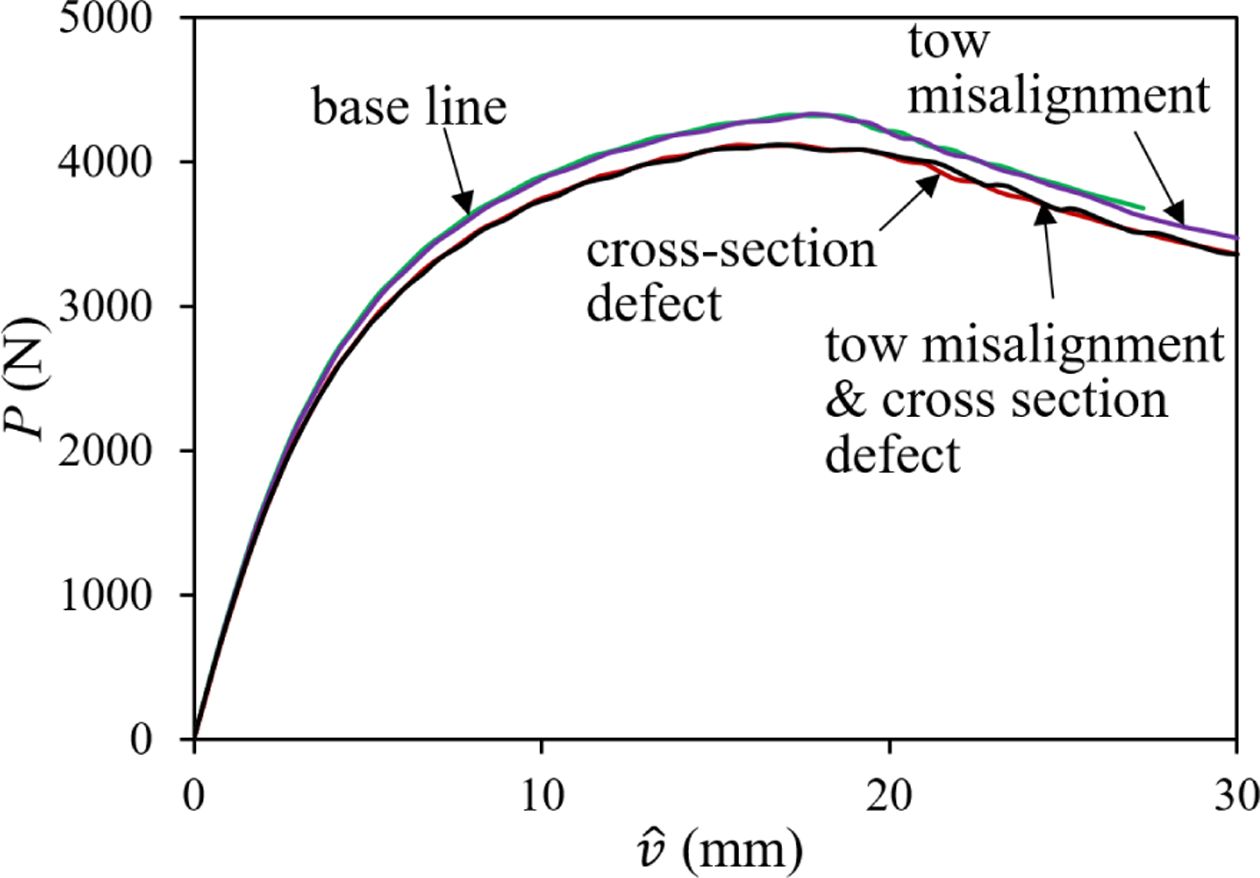
The
effect of the cross sectional and tow waviness defects was also studied.
Non-linear post-buckling analysis was also performed considering models with
different imperfections separately and combined. Fig. 16 shows predicted
numerical result with different types of imperfections considered separately
and combined compared with the baseline model result. Here the baseline model
refers to a model with averaged cross-sectional dimension and 3o specimen
tilting. As can be seen from the curves, the manufacturing defect in the form
of longitudinal tow waviness had very small effect. The ultimate buckling load
decreased by only 0.2%. In contrast, the buckling load with the cross-sectional
defect reduced by 4.8%. In addition to the buckling load and stiffness reduction
from cross-sectional defect, different buckling order was also resulted in
which is described in the next section.
4.4
Comparison of test and analysis results
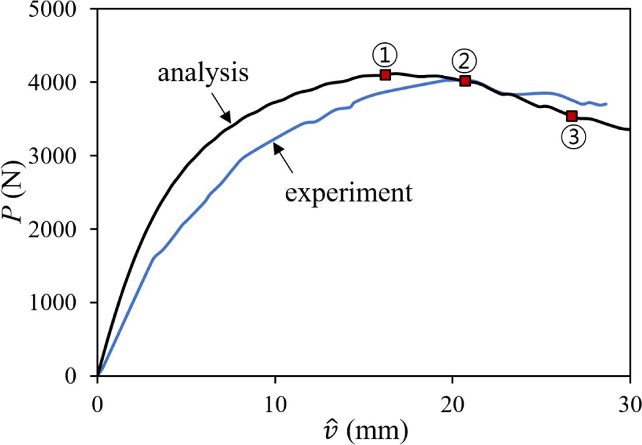
Fig.
17 compares the experimental load-displacement curve with the numerical
prediction considering all defects. Both results showed a good correlation with
the general trend matched. The predicted ultimate buckling load differs only by
2.3% compared to that by experiment.
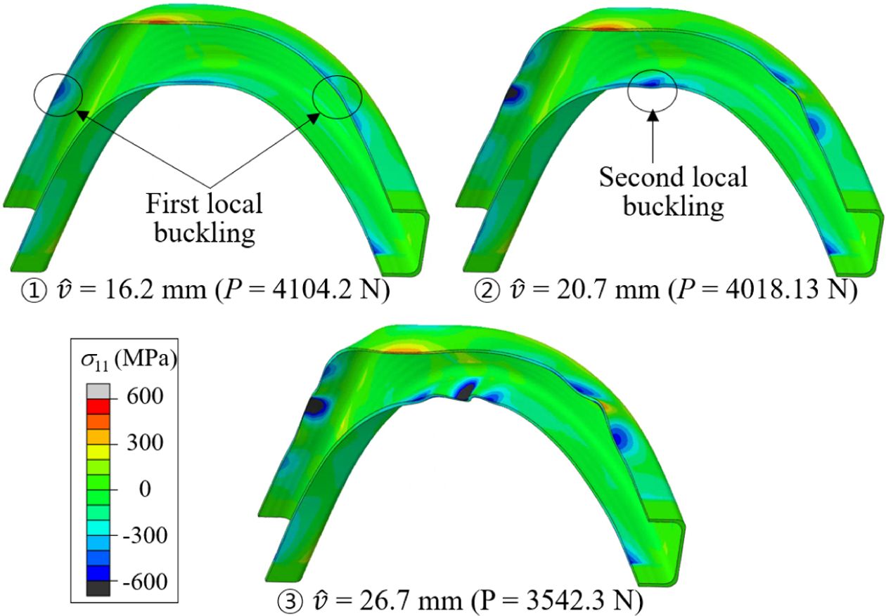
Compared
to the buckling behavior of the pristine model, a different buckling
development behavior was observed due to the inclusion of defects. Fig. 18 shows the buckling
deformation at three different loading stages corresponding to points indicated
by the circled numbers in the load-displacement curve. As the applied
displacement increase, the specimen initially showed the global bending out-of-plane
deformation (mode 1). Then, when the displacement loading increased to 16.2 mm,
local buckling started to develop at the upper flange between the support and
the crown, which was different from the pristine model where the first local
buckling appeared at the bottom flange of the crown part. Further increasing
the displacement to 20.7 mm, the second local buckling developed at the bottom
flange of the crown. After that, as the displacement increased the buckling
deformation at the side and at the crown grew higher order buckling modes
developing multiple waves.
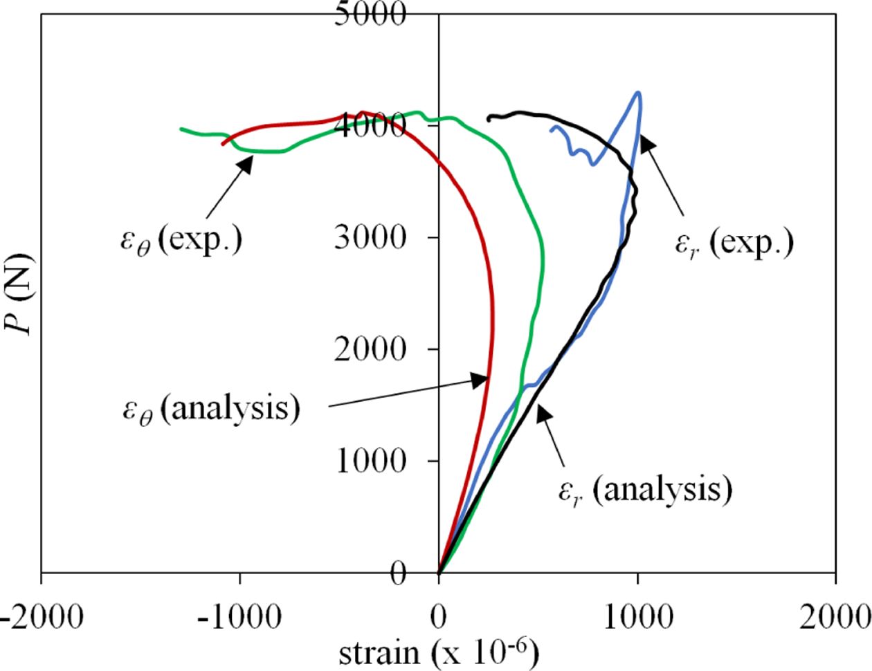
The
local deformation response from the strain gauges attached at the center of the
web midway between the supports in radial (εr) and
circumferential (εθ) direction was compared in Fig. 19. A good
qualitative correlation was obtained for both directional strain readings
despite the dependence of local reading to the presence of defect at that
location.
|
Fig. 8 Linear buckling modes (Disp. scale = 25) |
|
Fig. 9 Typical bending moment distribution of rectangular arch |
|
Fig. 10 Buckling mode for cross-sectional defect (Disp. scale =25) |
|
Fig. 11 Buckling modes for tow misalignment (Disp. scale = 25) |
|
Fig. 12 Predicted deformation history for pristine model |
|
Fig. 13 Predicted load-displacement for pristine model |
|
Fig. 14 Effect of tilting on post-buckling behavior |
|
Fig. 15 Effect of tilting on ultimate buckling load (left) and initial stiffness (right) |
|
Fig. 16 Load-displacement curves for defects and uncertainties |
|
Fig. 17 Comparison of predicted and test load-displacement curves |
|
Fig. 18 Nonlinear buckling history with all defects considered |
|
Fig. 19 Comparison of predicted and test load-strain curves |
In
this paper, the buckling behavior of triaxially braided composite arch frame
under three-point bending was investigated using experimental and numerical
approach. The manufacturing defects and uncertainty during test setup were
identified and their effect on the buckling performance of the specimen was
studied numerically. The predicted results were compared with the experimental
results for verification. It was found that the global first bending mode of
the composite circular arch was predicted to occur at the vertical load of
4771.4 N
by linear buckling analysis, however it started develop from the beginning in
geometrically nonlinear post-buckling analysis. In the geometrically nonlinear
post-buckling analysis, the ultimate buckling load occurred when the first
local buckling mode developed, indicating although the global buckling behavior
depended on the global stiffness of the composite circular arch, the ultimate
buckling load depended on the development of local buckling on top and bottom
flange. It was also found that the manufacturing defect in the form of
irregular cross section and imperfect test setup had significant effects on
both linear buckling and geometrically nonlinear post-buckling behavior, while
local tow misalignments had only minor effects. It was thought that the manufacturing
quality should be tightly controlled to avoid defects in the composite specimen
that could result in reduction in buckling loads and mode shape change.
This
work was supported by Defense Acquisition Program of Korea through Dual Use
Technology Development Project 2018.
- 1. Li, X., Binienda, W.K., and Goldberg, R.K., “Finite-element Model for Failure Study of Two-dimensional Triaxially Braided Composite,” Journal of Aerospace Engineering, Vol. 24, No. 2, 2010, pp. 170-180.
-

- 2. Xu, L., Kim, S.J., Ong, C.H., and Ha, S.K., “Prediction of Material Properties of Biaxial and Triaxial Braided Textile Composites,” Journal of Composite Materials, Vol. 46, No. 18, 2012, pp. 2255-2270.
-
- 3. Kosztowny, C.J., and Waas, A.M., “Buckling and Post-Buckling Behavior of Unitized, Stiffened Tri-Axially Braided Composite Textile Plates,” Proceeding of the 55th SDM Conference, Maryland, Jan. 2014.
-
- 4. Potdar, S.A., and Bajad, M.N., “Design Method Prediction for Flexural Torsional Buckling Re-sistance of Steel Circular Arches-Box-Section”, Journal of Modern Engineering Research, Vol. 6, Iss. 7, 2016, pp. 8-14.
- 5. Dou, C., Guo, Y.L., Zhao, S.Y., and Pi, Y.L., “Experimental Investigation into Flexural-torsional Ultimate Resistance of Steel Circular Arches,” Journal of Structural Engineering, Vol. 141, No. 10, 2015, pp. 1-12.
-
- 6. Guo, Y.L., Zhao, S.Y., Pi, Y.L., Bradford, M.A., and Dou, C., “An Experimental Study on Out-of-plane Inelastic Buckling Strength of Fixed Steel Arches,” Engineering Structures, Vol. 98, 2015, pp. 118-127.
-
- 7. Barbero, E., and Tomblin, J., “Euler Buckling of Thin-walled Composite Columns,” Thin-walled Structures, Vol. 17, No. 4, 1993, pp. 237-258.
-
- 8. Qiao, P., Zou, G., and Davalos, J.F., “Flexural–torsional Buckling of Fiber-reinforced Plastic Composite Cantilever I-beams,” Composite Structures, Vol. 60, No. 2, 2003, pp. 205-217.
-
- 9. Omidvar, B., and Ghorbanpoor, A., “Nonlinear FE Solution for Thin-walled Open-section Composite Beams,” Journal of Structural Engineering, Vol. 122, No. 11, 1996, pp. 1369-1378.
-
- 10. ASTM E1856-13, “Standard Guide for Evaluating Computerized Data Acquisition Systems Used to Acquire Data from Universal Testing Machines,” ASTM International, West Conshohocken, PA, 2013.
- 11. Hassan, N.K., and Mosallam, A.S., “Buckling and Ultimate Failure of Thin-walled Pultruded Composite Columns,” Polymers and Polymer Composites, Vol. 12, No. 6, 2004, pp. 469-481.
- 12. Lee, J.H., and Kim, S.E., “Flexural–torsional Buckling of Thin-walled I-section Composites,” Computers & Structures, Vol. 79, No. 10, 2001, pp. 987-995.
-
- 13. Arbelo, M.A., Kalnins, K., Ozolins, O., Skukis, E., Castro, S.G.P., and Degenhardt, R., “Experimental and Numerical Estimation of Buckling Load on Unstiffened Cylindrical Shells Using a Vibration Correlation Technique,” Thin-Walled Structures, Vol. 94, 2015, pp. 273-279.
-
- 14. Hosseini-Toudeshky, H., Hosseini, S., and Mohammadi, B., “Delamination Buckling Growth in Laminated Composites Using Layerwise-interface Element,” Composite Structures, Vol. 92, No. 8, 2010, pp. 1846-1856.
-
- 15. Schenk, C.A., and Schuëller, G.I., “Buckling Analysis of Cylindrical Shells with Random Geometric Imperfections,” International Journal of Non-Linear Mechanics, Vol. 38, No. 7, 2003, pp. 1119-1132.
-
- 16. Sadovský, Z., Kriváček, J., Ivančo, V., and Ďuricová, A., “Computational Modelling of Geometric Imperfections and Buckling Strength of Cold-formed Steel,” Journal of Constructional Steel Research, Vol. 78, 2012, pp. 1-7.
-
- 17. Mekonnen, A.A., and Woo, K., “Effects of Defects on Effective Material Properties of Triaxially Braided Textile Composite”, Submitted to International Journal of Aeronautical and Space Sciences, 2019.
- 18. ASTM D3039/D3039M-17, “Standard Test Method for Tensile Properties of Polymer Matrix Composite Materials,” ASTM International, West Conshohocken, PA, 2017.
- 19. Alpha STAR Corporation, MCQ-Composites Theoretical Manual, Alpha STAR Corporation, 2014.
- 20. Geleta, T.N., Woo, K.S., and Lee, B.H., “Prediction of Effective Material Properties for Triaxially Braided Textile Composite,” International Journal of Aeronautical and Space Sciences, Vol. 18, No. 2, 2017, pp. 222-235.
 This Article
-
2019; 32(5): 249-257
Published on Oct 31, 2019
- 10.7234/composres.2019.32.5.249
- Received on May 15, 2019
- Revised on Oct 5, 2019
- Accepted on Oct 10, 2019
Services
- Abstract
introduction
experiment
analysis
results and discussion
conclusions
acknowledgement
- References
- Full Text PDF
Shared
Correspondence to
- Kyeongsik Woo
-
School of Civil Engineering, Chungbuk National University
- E-mail: kw3235@chungbuk.ac.kr
Gangnam Mirae Tower, Suite 601, 174 Saimdang-ro, Seocho-gu, Seoul 06627, South Korea
Tel: +82-2-598-1550 Fax: +82-2-598-1557 E-mail: composites@kscm.re.kr