


- Unit Cell FEM Analysis Using I-Fiber Single Stitch with Different Thickness
Jonathan Tapullima*, Gyu Yeong Park*, Dong Hwan Yoon*, Jin Ho Choi*†
* Research Center for Aircraft Parts Technology, School of Mechanical and Aerospace Engineering, Gyeongsang National University
This article is an open access article distributed under the terms of the Creative Commons Attribution Non-Commercial License (http://creativecommons.org/licenses/by-nc/4.0) which permits unrestricted non-commercial use, distribution, and reproduction in any medium, provided the original work is properly cited.
This paper present a three-dimensional unit cell finite element analysis to predict the pull-out behavior of a single stitch in a composite laminate. The stitching process used for this study correspond to the I-fiber stitching method that has been studied by the Composite Structures Lab (CSL) as a new through-thickness reinforced method. A total of six cases were analyzed, which were divided in two groups by the stitching yarn used, 6k and 12k. Each group of cases have three different thickness according to the amount of plies; 16 plies, 32 plies and 64 plies. The finite element analysis used the cohesive zone method to characterize the single stitch reinforcement in the interface. Due to the complexity of the load vs displacement curves taken from the experimental results, a bilinear and trilinear bridging laws were implemented in the models. The cohesive parameters used for each case showed a good agreement with the experimental data and can be used for future studies.
Keywords: I-fiber stitching, Pull-out, Unit cell, CZM (Cohesive Zone Method)
The development in composites materials for several industries requires reliable adhesives and joints in order to assemble several parts. However, it is difficult to apply these mechanical joints to composite materials, because fastener holes can break fibers and cause local delamination and cracks in the material’s matrix, decreasing the strength in the through-thickness direction [1]. Therefore, several methods have been developed to increase the through-thickness strength of bonded joints, such as stitching, braiding, tufting, weaving, and z-pinning; all these methods have been studied with the goal of identifying the best method for structure reinforcement [2-7].
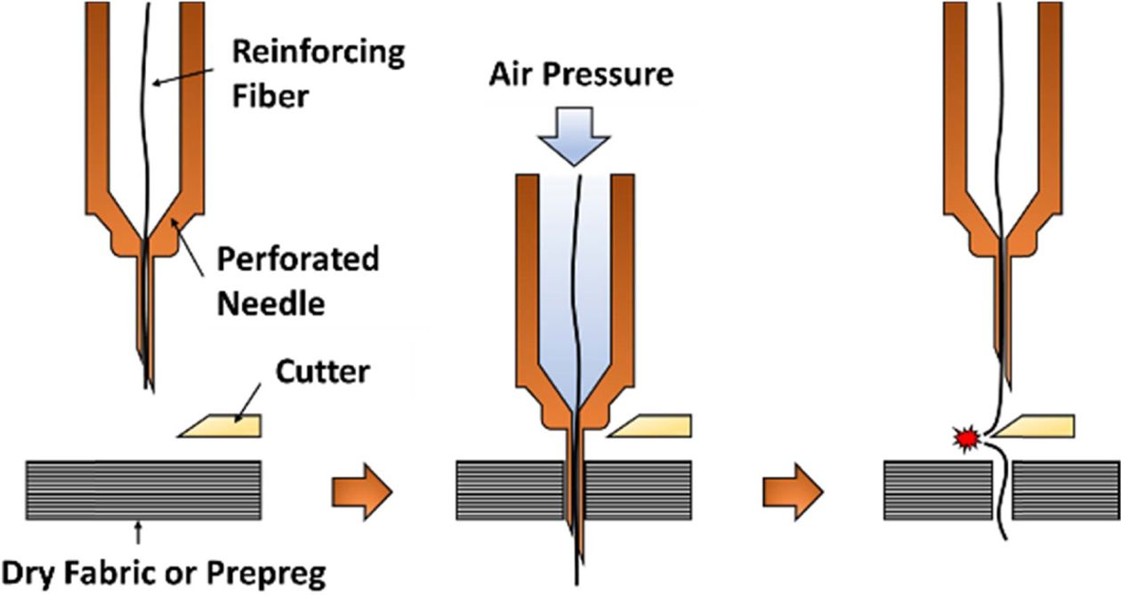
A novel stitching technique was developed to increase the strength of laminated composites in the thickness direction which is called the I-Fiber stitching method [8]. The I-Fiber name came from the discontinue stitching process, providing an upper and lower “head” to the reinforced stitch. Fig. 1 show a schematic of the I-Fiber stitching process in detail. Several studies has been performed that shown the mechanical properties of this reinforcement method [9-13].
Based on a previous analysis where DCB specimens where testes to understand the mode I properties of the I-fiber [9,10], this analysis focus on the micro-mechanical behavior of a single stitch using a unit-cell specimen to obtain the pull-out response for a better understanding of the I-fiber mechanical properties.
To design a numerical model, the cohesive zone method (CZM) was used, three-dimensional elements were modeled in the center of the unit cell interface as the stitch. Cohesive elements are widely used to simulate crack propagation and delamination. The bridging or cohesive law that define the numerical model can be used to simulate reinforcement and depending on the bridging response, the cohesive law can be specified as bilinear, trilinear or higher response, depending on the mechanical behavior.
This study took unit-cell experimental results using 6k and 12k stitching yarns, which were stitched in three different laminates thickness with 16 plies, 32 plies and 64 plies, giving a total of six cases. The results allowed to obtain the cohesive parameters needed to simulate macro-scale models of complex reinforced structures using the I-fiber stitching method.
|
Fig. 1 I-fiber stitching method schematic process |
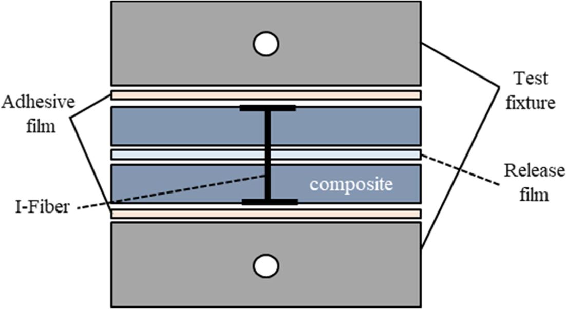
The modeling explained in section 4 and results discussed in section 5 were supported by test of unit-cell single I-fiber stitch specimens subjected to pull-out load with six different cases performed by the Composite Structures Lab. (CSL) at Gyeongsang National University [14]. Fig. 2 presents the specimen configuration used for the mechanical tests. The specimen consists of a top half-laminate, a bottom half-laminate and a single I-fiber stitch. The two half laminates were separated by a release film with 0.03 mm of thickness on the mid-plane and bridged only by the single stitch inserted in the center through the thickness of the laminate. The mechanical loads were applied using a steel jig bonded on the top and bottom of the specimen.
The equipment used for the experiment was a Z010TN (ZWICK Co.) testing machine with 10 KN of loading capacity. The experiment was performed with a cross-head speed of 0.1 mm/min for all of the cases.
|
Fig. 2 Schematics of unit-cell specimen for single stitch pull-out test |
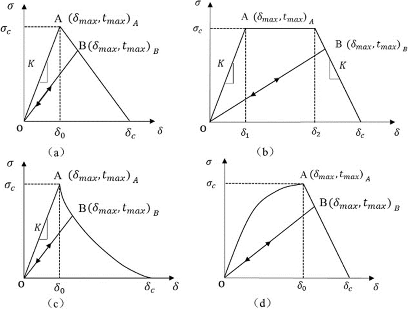
Based on previous studies using 3D cohesive elements [15-18], a similar approximation with unit-cell is presented in this study. However, based on the experimental results, the load vs displacement curve showed different tendencies. The CZM present different cohesive traction separation law that can be employed according with curve response. Fig. 3 shown some separations laws commonly used [19].
3.1 Bilinear Response
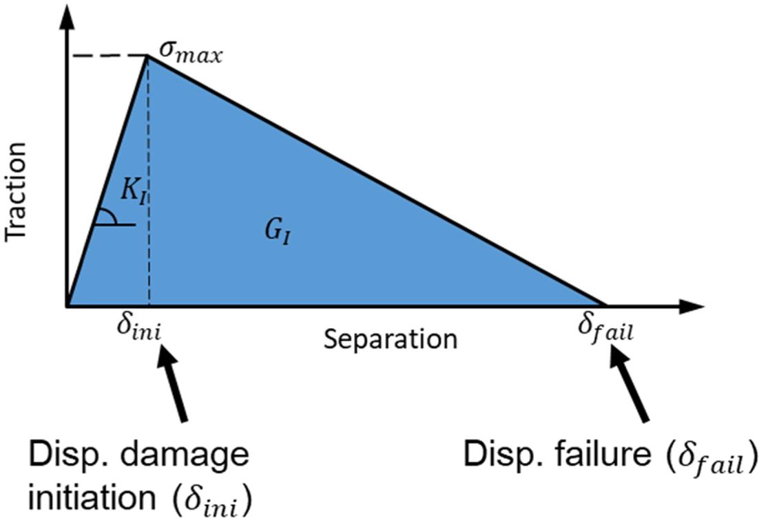
The traction-separation law with bilinear behavior proposed by Alfano and Crisfield [20] is represented in Fig. 4, where the maximum traction smax is reached when the damage starts, while δfail indicates the complete failure of the cohesive elements. KI Represents the cohesive stiffness and GI the fracture toughness for mode I. smax and KI is calculated as follow:
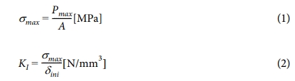
where Pmax is the failure load and A is the stitch cross section area. To define KI, in Eq. 2, δini is the displacement at dame initiation. However, in this study the FEA was performed using the platform Abaqus, for this reason, the cohesive stiffness is defined as follow:
where En is the elastic constant and heff is the cohesive geometrical thickness, in the experiments the value represents the release film thickness. From the bilinear response, GI can be obtained as follow:
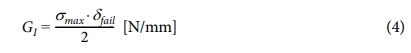
The tree main parameters that define the cohesive law in a bilinear response are: σmax, En and GI.
3.2 Trilinear Response
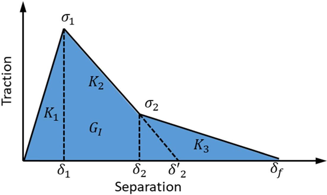
The traction separation law for a trilinear response is defined as a tabular form, where independent on the response grade, each section have a different cohesive stiffness and as shown in Fig. 5 [21,22]. The cohesive law is based on the damage evolution equation and is defined by the damage variable D and the displacement δ:
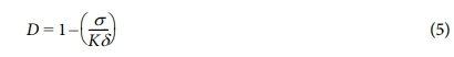
where D is zero until the damage initiation is reached. Fig. 5 show a schematic of the trilinear response.
From Fig. 5, the following system of equations to obtain the traction were derived as follow:
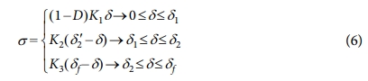
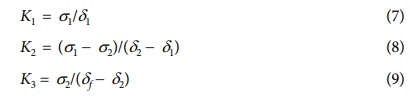
To calculate the stiffness in every stage of the response, the following equations were used:
|
Fig. 3 Different examples of cohesive traction separation law (a) triangular CZM, (b) trapezoidal CZM, (c) linear–exponential CZM, and (d) exponential–linear CZM |
|
Fig. 4 Schematic of the bilinear response |
|
Fig. 5 Schematic of the trilinear response |
In order to validate the modeling proposed in this micro-mechanical reinforcement, six different cases with H2550 yarns stitched in USN-125B unit-cell composite laminates were investigated.
4.1 Material Definition
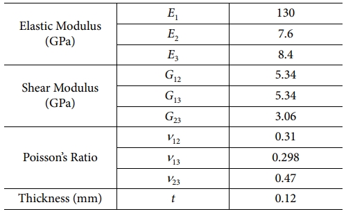
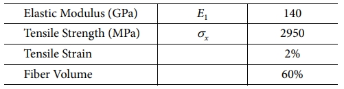
A total of six cases were analyzed, divided in two groups by the stitching yarn, 6k and 12k yarn. The material used for the stitched yarn was Hyosung Tansome H2550. Three different laminates were analyzed and the thickness varies with the stacking sequence for 16 plies, 32 plies and 64 plies with the following staking sequence; 16-ply: [[0/-45/90/45]S]S, 32-ply: [[0/-45/90/45]2S]S and 64-ply: [[0/-45/90/45]4S]S. The stitched composite laminates unit-cell were manufactured using carbon prepreg from SK Chemicals USN-125B. Table 1 shows the prepreg properties and Table 2 shows composite properties of the stitched yarn.
Based on microscopic analysis to evaluate the stitch cross section area, the cohesive area were defined for both kind of yarn in all the modeling cases. The I-fiber cross section area for 6k and 12k are 0.97 mm² and 1.58 mm² respectively [13].
4.2 Mesh Generation
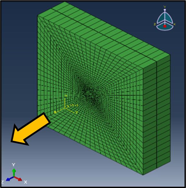
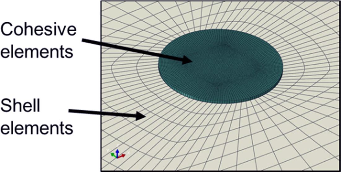
The unit-cell modeling was defined for all cases in three main bodies, the top and bottom half-laminate and the stitching yarn that was defined with 3D cohesive elements which were tied with the adjacent hal-laminate. The composite laminate consisted of 8-nodes continuum shell elements with reduced integration (SC8R) and the stitched yarn contained 3D cohesive elements with 8-nodes (COH3D8). Note that one shell element per half-laminate in the thickness direction was used as is shown in Fig. 6 where the arrow indicates the loading direction.
The models were analyzed in the commercial FE package Abaqus/Standard. There were 5,760 eight-node shell elements, and 3,520 cohesive elements and 18,886 total nodes in the model. A 0.03 mm (half ply thickness) gap is introduced between the two half-laminates to simulate the release film in the middle used in the experiments. In order to achieve numerical stability the cohesive elements size were one-fourth of the adjacent shell element size [23]. Fig. 7 shown the detail of the cohesive elements over the laminate. The unit-cell model had a dimension of 1.5 cm × 1.5 cm.
|
Fig. 6 Unit-cell modeling 32 plies case |
|
Fig. 7 Detail view of the 3D cohesive elements attached to the laminate shell elements |
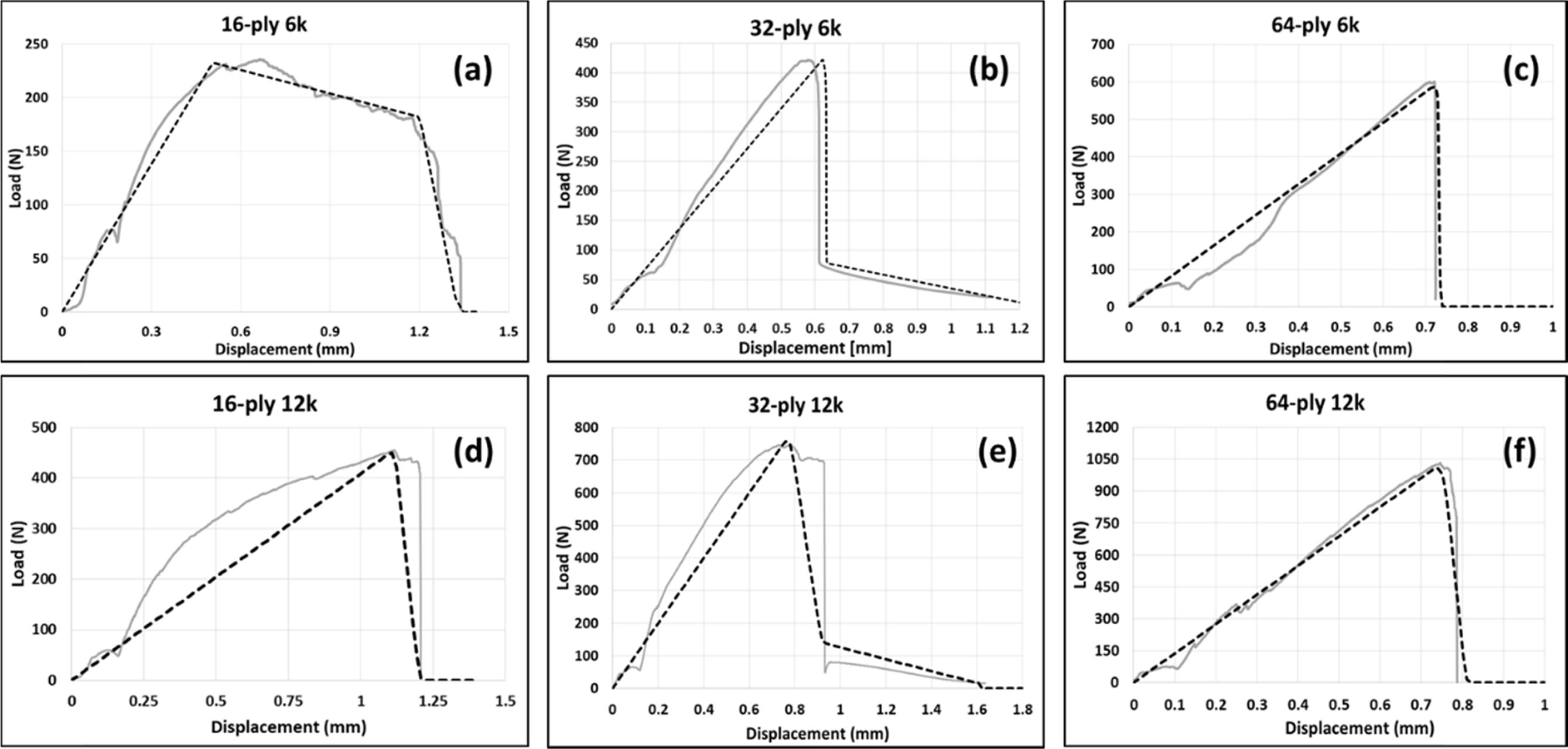
For the laminates stitched with 6k yarn and based on the cross section area of the yarns, the maximum traction values were calculated (Eq. 1). For 16-ply case the maximum traction was 243 MPa, for 32-ply was around 434 MPa, while for 64-ply was 618 MPa. This shown a higher strength perform using the same yarn when the laminate thickness increase. The fracture toughness for 16-ply, 32-ply and 64-ply was 224 N/mm, 161 N/mm and 222 N/mm respectively. This variation represent a higher friction between the yarn and the resin around the 16-ply case shown in Fig. 8a and a lower but existing friction effect was evidenced in the 32-ply results (Fig. 8b). In both cases a trilinear cohesive law were used to define the bridging response while for 64-ply results an abrupt failure occurred without friction effect (Fig. 8c) and a bilinear cohesive law was employed.
In the same way, the results obtained from the unit-cells stitched with 12k yarn showed a maximum traction of 288 MPa with a fracture toughness of 173 N/mm and an abrupt failure for the 16-ply case, therefore a bilinear response was calculated (Fig. 8d). Fig. 8f show 32-ply case, where the maximum traction was around 440 MPa with a fracture toughness of 237 N/mm, however a small friction response were observed and a trilinear cohesive law was calculated as shown in Fig. 8e. While for 64-ply case, the traction was 653 MPa and a fracture toughness of 264 N/mm, the failure behavior was abrupt and a bilinear cohesive law was employed to define this case.
|
Fig. 8 Summary of the load vs displacement curves obtained from experimental data (grey lines) and compared with finite element analysis (dash lines) |
Based on experimental data, several FEM analysis were con-ducted to simulate the behavior of a single stitch unit-cell for six different cases using the I-fiber stitching method. Prior calculation was needed to define the traction-separation law and identify the cohesive response based on the load vs displacement curve shape using the damage variable as a main input parameter. FEM results shown a good agreement with the experimental results. The debonding, pull-out friction and final failure of the stitch was simulated using the cohesive law.
This work was supported by the National Research Foundation of Korea (NRF) Grant funded by the Ministry of Science, ICT & Future Planning (NRF-2017R1A5A1015311).
- 1. Ji, H., Kweon, J.H., and Choi, J.H., “Fatigue Characteristics of Stainless Steel Pin-reinforced Composite Hat Joints,” Journal of Com-posite Structures, Vol. 108, 2014, pp. 49-56.
-

- 2. Jones, R.M., Mechanics of Composite Materials 2nd edition, Taylor & Framcis Inc, 1999.
- 3. Mouritz, A.P., Bannister, M.K., Falzon, P.J., and Leong, K.H., “Review of Applications for Advanced Three-dimensional Fibre Tex-tile Composites”, Journal of Composites Part A, Vol. 30, No. 12, 1999, pp. 1445-1461.
-
- 4. Ayranci, C., and Carey, J., “2D Braided Composites: A Review for Stiffness Critical Applications,” Journal of Composite Structures, Vol. 85, No. 1, 2008, pp. 43-58.
-
- 5. Chou, S., and Chen, H.E., “The Weaving Methods of Three-dimensional Fabrics of Advanced Composite Materials,” Journal of Composite Structures, Vol. 33, No. 3, 1995, pp. 159-172.
-
- 6. Chi, H., Li, Y., Koussios, S., Zu, L., and Beukers, A., “Bridging Micromechanisms of z-pin in Mixed Mode Delamination,” Journal of Composite Structures, Vol. 93, No. 11, 2011, pp. 2685-2695.
-
- 7. Ko, F.K., Three-dimensional Fabrics for Composites, Composite Materials Series. Amsterdam: Elsevier Science, 1989.
- 8. Kim, C.H., Jo, D.H., and Choi, J.H., “Failure Strength of Composite T-joint Prepared Using a New 1-thread Stitching Process,” Journal of Composite Structures, Vol. 178, 2017, pp. 225-231.
-
- 9. Tapullima, J., Kim, C.H., and Choi, J.H., “Analysis and Experiment on DCB Specimen Using I-fiber Stitching Process,” Journal of Composite Structures, Vol. 220, 2019, pp. 521-528.
-
- 10. Tapullima, J., Sim, H.W., Kweon, J.H., and Choi, J.H., “Analysis on Stitched Mode I Specimen Using Spring Elements,” Composites Research, Vol. 32, No. 2, 2019, pp. 102-107.
-
- 11. Kim, C.H., Sim, H.W., An, W.J., Kweon, J.H., and Choi, J.H., “Impact Characteristics of Composite Panel Stitched by I-fiber Pro-cess,” Journal of Composites Part A, Vol. 127, 2019, pp. 105644.
-
- 12. An, W.J., Kim, C.H., Choi, J.H., and Kweon, J.H., “Static Strength of RTM Composite Joint with I-fiber Stitching Process,” Journal of Composite Structures, Vol. 210, 2019, pp. 348-353.
-
- 13. Tapullima, J., Song, S.H., Kweon, J.H., and Choi, J.H., “Characterization of Mode II Specimen Using I-fiber Stitching Process,” Journal of Composite Structures, Vol. 225, 2021, pp. 112863.
-
- 14. Park, G.Y., “Evaluation and Analysis of Mode I Failure Load for Single Stitched Fiber,” Master Thesis, Gyeongsang National Univer-sity, 2020.
- 15. Yan, Y., and Shang, F., “Cohesive Zone Modeling of Interfacial Delamination in PZT Thin Films,” International Journal of Solids and Structures, Vol. 46, No. 13, 2009, pp. 2739-2749.
-
- 16. Kravchenko, S., Krsvchenko, O., Wortmann, M., Pietrek, M., Horst, P., and Pipes, R.B., “Composite Toughness Enhancement with Interlaminar Reinforcement,” Journal of Composites Part A, Vol. 54, 2013, pp. 98-106.
-
- 17. Bianchi, F., and Zhang, X., “A Cohesive Zone Model for Predicting Delamination Suppression on z-pinned Laminates”, Composites Science and Technology, Vol. 71, No. 16, 2011, pp. 1898-1907.
-
- 18. Mohamed, G., Allegri, G., Yasaee, M., and Hallett, S.R., “Cohesive Element Formulation for z-pin Delamination Bridging in Fibre Reinforced Laminates,” International Journal of Solids and Structures, Vol. 132-133, 2017, pp. 232-244
-
- 19. Heidari-Rarani, M., and Ghasemi, A.R., “Appropriate Shape of Cohesive Zone Model for Delamination Propagation in ENF Speci-mens with R-curve Effects,” Theoretical and Applied Fracture Mechanics, Vol. 90, 2017, pp. 174-181.
-
- 20. Alfano, G., and Crisfeld, M.A., “Finite Element Interface Models for the Delamination Analysis of Laminated Composites: Mechan-ical and Computational Issues,” International Journal for Numerical Methods in Engineering. Vol. 50, No. 7, 2001, pp. 1701-1736.
-
- 21. Islam, M.S., “Fracture and Delamination in Packaging Materials,” PhD Thesis, Blekinge Institute of Technology, 2019.
- 22. Gutkin, R., Laffan, M.L., Pinho, S.T., Robinson, P., and Curtis, P.T., “Modelling the R-curve Effect and Its Specimen-dependence,” International Journal of Solids and Structures, Vol. 48, No. 11-12, 2011, pp. 1767-1777.
-
- 23. Diehl, T., “On Using a Penalty-based Cohesive-zone Finite Element Approach, Part II: Inelastic Peeling if an Epoxy-bonded Alu-minium Strip,” International Journal of Adhesion and Adhesives, Vol. 28, No. 4-5, 2008, pp. 256-265.
-
 This Article
-
2021; 34(1): 30-34
Published on Feb 28, 2021
- 10.7234/composres.2021.34.1.030
- Received on Dec 22, 2020
- Revised on Feb 10, 2021
- Accepted on Feb 26, 2021
Services
- Abstract
1. introduction
2. experimental characterization
3. modeling method
4. case study for validation
5. results and discussion
6. conclusions
- Acknowledgements
- References
- Full Text PDF
Shared
Correspondence to
- Jin Ho Choi
-
Research Center for Aircraft Parts Technology, School of Mechanical and Aerospace Engineering, Gyeongsang National University
- E-mail: choi@gnu.ac.kr
Gangnam Mirae Tower, Suite 601, 174 Saimdang-ro, Seocho-gu, Seoul 06627, South Korea
Tel: +82-2-598-1550 Fax: +82-2-598-1557 E-mail: composites@kscm.re.kr