


- 3D Weaving Process : Development of Near Net Shape Preforms and Verification of Mechanical Properties
Vinzenz Klapper*, **, ***, Kwang-Hoon Jo*, Joon-Hyung Byun*, Jung-Il Song**, Chee-Ryong Joe**†
* KIMS, Functional Composites Research Division, Korea Institute of Materials Science, Changwon, Korea
** School of Mechanical Engineering, Changwon National University, Changwon, Korea
*** LSTME Busan, Department of Fluid Mechanics, Busan, KoreaThis article is an open access article distributed under the terms of the Creative Commons Attribution Non-Commercial License (http://creativecommons.org/licenses/by-nc/4.0) which permits unrestricted non-commercial use, distribution, and reproduction in any medium, provided the original work is properly cited.
The lightweight industry continuously demands reliable near-net-shape fabrication where the preform just out-of-machine is close to the final shape. In this study, different half-finished preforms are made π-beams. Then the preforms are unfolded to make a 3D shape with integrated structure of fibers, providing easier handling in the further processing of composites. Several 3D textile preforms are made using weaving technique and are examined after resin infusion for mechanical properties such as inter-laminar shear strength, compressive strength and tensile strength. Considering that the time and labor are important parameters in modern production, 3D weaving technique reduces the manufacturing steps and therefore the costs, such as hand-lay up of textile layers, cutting, and converting into preform shape. Hence this 3D weaving technique offers many possibilities for new applications with efficient composite production
Keywords: 3D weaving, weave pattern, π-beam, T-joint
To reduce the product weight and material cost, the lightweight industry is continuously demanding a preform that is close to the final product shape and easy to produce. Common processes are 3D weaving, round knitting, pultrusion, or joint-forming process between metal and preform [1]. Conventional woven fabrics normally consist of warp and fill yarn that interlace with each other to form a 2D textile. In the case of 3D woven textiles, fill yarns form two or more layers that are connected by warp yarns delivered by a spool rack. New modeling possibilities are continuously discovered using 3D weaving [2]. Within the 3D weaving process different layers can be interconnected completely or partially. Non-interconnected layers can build two or more bifurcations [3]. This high degree of modification opportunities makes it possible to nearly customize the mechanical properties of the final preform. Therefore, various weaving pattern and layer-interconnections can be used for a specific application. The variation of the interconnection in position and length by the warp yarn is offering many possibilities to create 3D textile preforms. With 3D weaving techniques, many integrated structural solutions such as different beam types and stiffeners can be produced [4]. Since weaving machines generally produce continuous textiles, the 3D preforms are connected by warp fibers and need to be separated after production.
1.1 General Aspects of 3D Woven Preforms
Every 3D textile preform manufacturing technique has its limitations. The braiding process limits the radial size while the weaving of a 3D preform limits the final preform size in its length that is equal to the width of the woven fabric produced by the weaving machine [5]. While 2D textile preforms offer good mechanical in-plane properties, 3D textile preforms exhibit good mechanical properties in z-direction since they are additionally reinforced in the thickness direction. The strength and stiffness of the 3D woven composite material differ by several parameters such as:
• yarn size
• weave pattern
• crimp angle
• fiber volume fraction
• ratio of warp and fill yarn content [6].
A thicker yarn generally leads to higher stiffness and strength, while a plain weave pattern offers less stiffness compared to a twill weave pattern due to higher yarn crimp. Often an earlier tensile failure can occur in high crimped 2D textiles since the matrix fails because of the straightening of the fiber during the tensile test [7]. Crimped 3D textiles that are reinforced in the thickness direction mostly do not show an early matrix failure since the yarn penetrating the plane holds the layers together and supports the crimp against straightening. This integrity of the layers can be achieved by several 3D weave reinforcement pattern [8] such as:
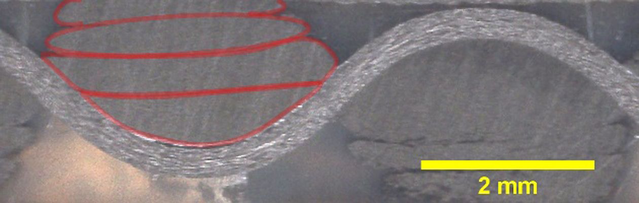
1. Orthogonal (ORT): Warp yarns, which are orthogonal to the plane direction, hold layers together as shown in Fig. 1.
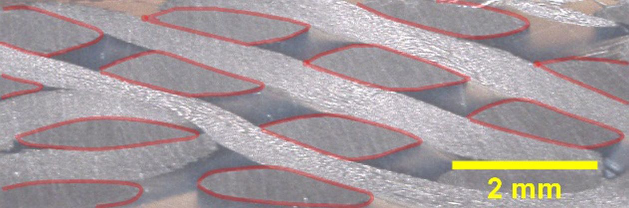
2. Through-the-thickness (TTT): Warp yarns integrate the layers together by reaching through the whole thickness of the plane as shown in Fig. 2.
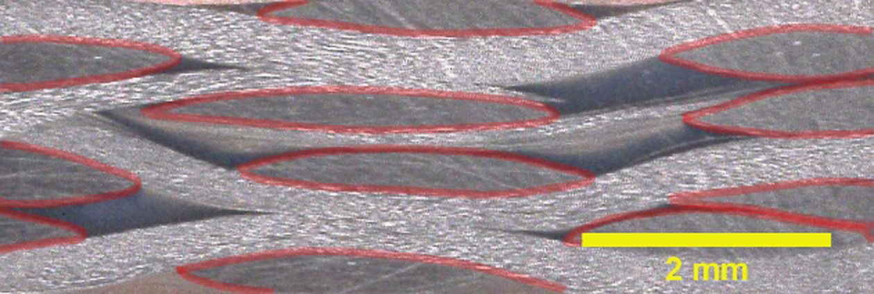
3. Layer-to-layer (LTL): Warp yarns combine the layers by reaching through several layers but not through the whole thickness of the textile as shown in Fig. 3.
Through-the-thickness weaving, orthogonal and layer-to-layer weaving are the most widely used 3D weaving pattern [9]. All these pattern can be created by a conventional weaving loom. The true orthogonal 3D weave in which fibers are combined in x, y and z-direction requires a special weaving loom [10]. This weaving technique is not considered here.
1.2 Material Strength of Different 3D Preform Pattern
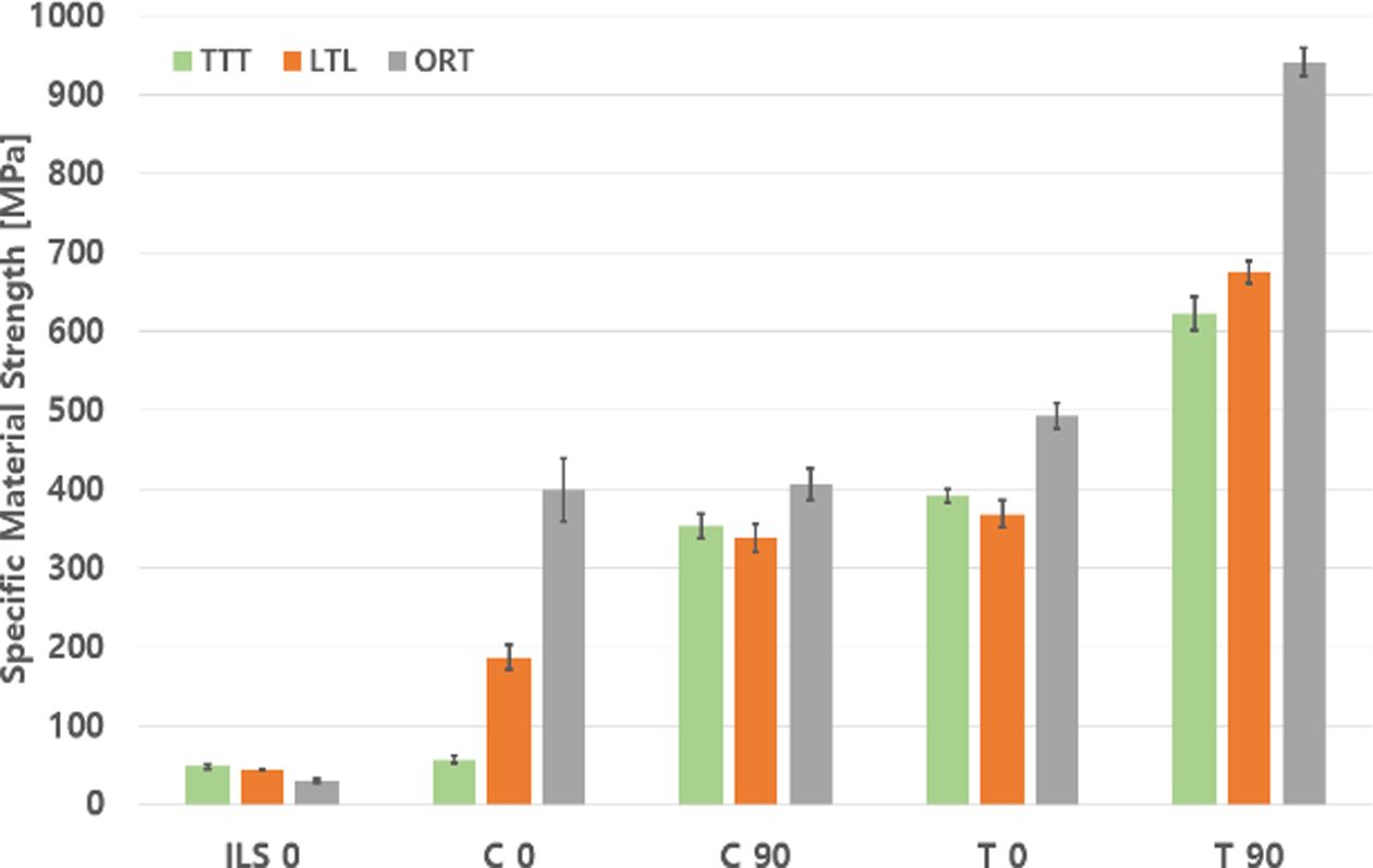
All the above-mentioned 3D weaving pattern are produced on a conventional weaving loom using 12k carbon fiber yarn with a standard elasticity modulus of T700. The weaving machine is located at Songwol Tech. in Sacheon, Korea. The woven materials are infused with epoxy resin EP2400 from Cytec. Afterward, the composite panel is cut to manufacture specimen. The mechanical tests are conducted at Korea Institute of Material Science (KIMS) in Changwon, Korea using ASTM D3039, ASTM D3410 and ASTM D2344. It is observed that the ORT weaving pattern provides significantly higher strength values in tensile and compression properties as shown in Fig. 4. In the shear direction, the LTL pattern has 50% higher strength than the ORT pattern while the TTT pattern offers 10% higher strength values than LTL. Since the ORT weave pattern exhibits better mechanical strength in fill yarn direction, the mean value can be seen around 45% higher than for the TTT and LTL weave pattern.
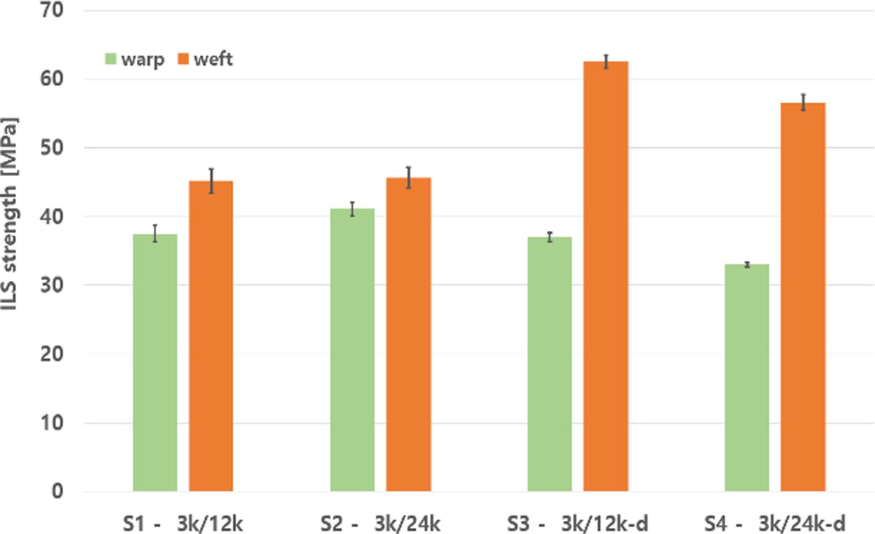
Furthermore, the compression strength in fill yarn direction, as well as the tensile strength in warp yarn direction, provide 30% higher values than the TTT and LTL pattern. The measured values are similar to previous findings [11]. Finally, the material strength of the ORT in the warp yarn compression is exceeding by almost 100% due to meandered warp yarn arrangement that surrounds the fill yarn. Better mechanical properties than TTT and LTL fabric make the ORT 3D weave pattern an excellent reinforcement in 3D textile preforms for numerous applications. Therefore, the ORT weave pattern is chosen for further investigation and improvements. Since the main target is to achieve higher material strength, the easiest approach is to improve the fiber volume fraction of the composite or use carbon fiber roving providing higher filament strength. Therefore, resin pockets need to be reduced and current carbon fiber yarn T700 (Toray) are replaced with T800 grade yarn of H3055 (Hyosung) with the same amount of filament filaments (sample S3). To reduce the number of resin pockets two 3k-filament warp yarn are added every 8th 12k-filament warp yarn at the spool rack and along with the weaving pattern. Furthermore, a second textile type is woven using 24k-fill yarn and comparing ILS strength of all woven types (Fig. 5).
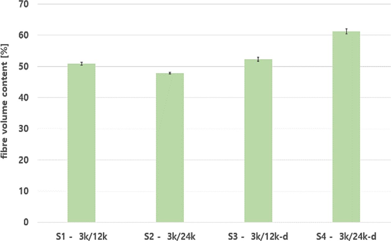
A higher ILS strength is measured for sample S3 (T800) while the replacement of 12k fill yarn with 24k fill yarn (sample S2 and S4) show a reduction of the ILS strength. It is also observed that densification of the preform during the weaving process leads to a higher ILS strength as well. The most efficient densification process needs to be evaluated iteratively since a malfunction of the mechanism of the weaving machine can occur during high densification (e.g. cutting malfunction of the fill yarn, buckling of the woven preform on the weaving loom). The sizes of the unit cells before and after the densification are measured to calculate the densification rate. It is found that the new preform could be woven 47% denser than before. Fig. 6
|
Fig. 1 ORT-weaving cross-section |
|
Fig. 2 TTT-weaving cross-section |
|
Fig. 3 LTL-weaving cross-section |
|
Fig. 4 Strength comparison of different weaving pattern: ILS (Interlaminar shear strength); C (Compressive strength); T (Tensile Strength); 0 (warp yarn direction); 90 (fill yarn direction) |
|
Fig. 5 ILS strength: sample 1 (12k, warp/12k, fill), sample 2 (12k, warp/ 24k, fill), sample 3 and 4: a dense setup (12k, warp/ 12k, fill) and (12k, warp/24k, fill) |
|
Fig. 6 Fiber volume fraction for different 3D-woven preforms |
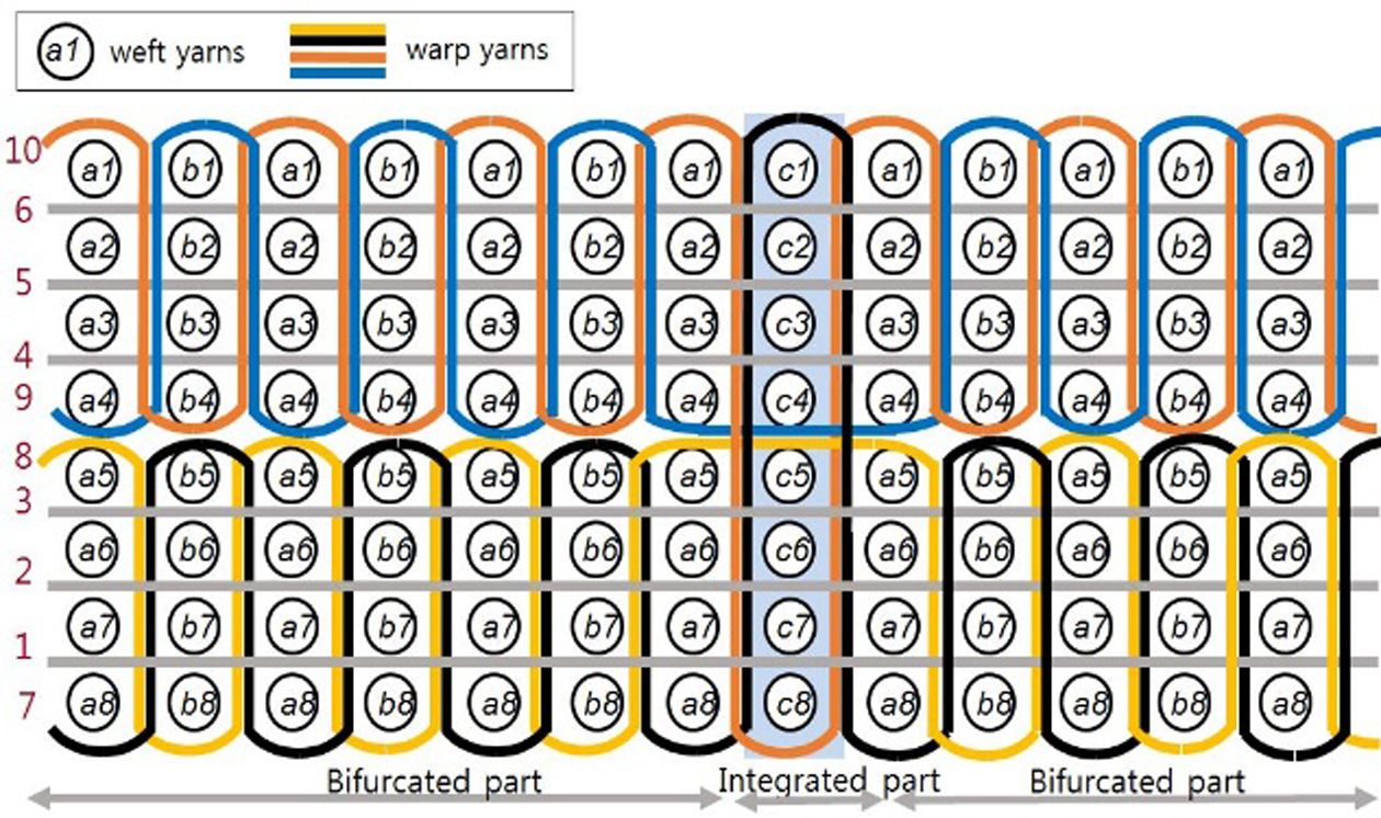
Since the dense ORT-woven preform type with 3k and 12k-warp yarn and 12k-fill yarn offer the highest tensile and compression strength results, this weaving setup is chosen for manufacturing the π-beam. To surround the two layers of the π-beam evenly, two more 12k yarn are placed along the preform width. They are numbered in Fig. 7 as numbers 8 and 9. The π-beam consists of two layers that are woven parallel to each other and are interconnected in the center. One of the layers can be used as the flange of the beam while the other layer will form the ‘legs’ of the π-beam when bended parallel around the interconnection.
|
Fig. 7 Yarn arrangement of the π-beam |
After the weaving process, the preform is trimmed so that the interconnected π-beams out of the weaving machine can be separated. Once the integrity of the beam preform is confirmed, the resin infusion process is initiated. A polished stainless-steel plate is used as ground for the beam. Under the vacuum bag, two aluminum blocks are holding the beams legs and flange rectangular while a thin aluminum plate of 5 mm thickness ensures the proper distance of the legs. A flow media, peel ply, sealing tape, PU inlets and outlets, and two vacuum bags are used to maintain a proper infusion process. The resin type EP2400 from Cytec is used for the infusion which cures at 180oC for 2 hours.
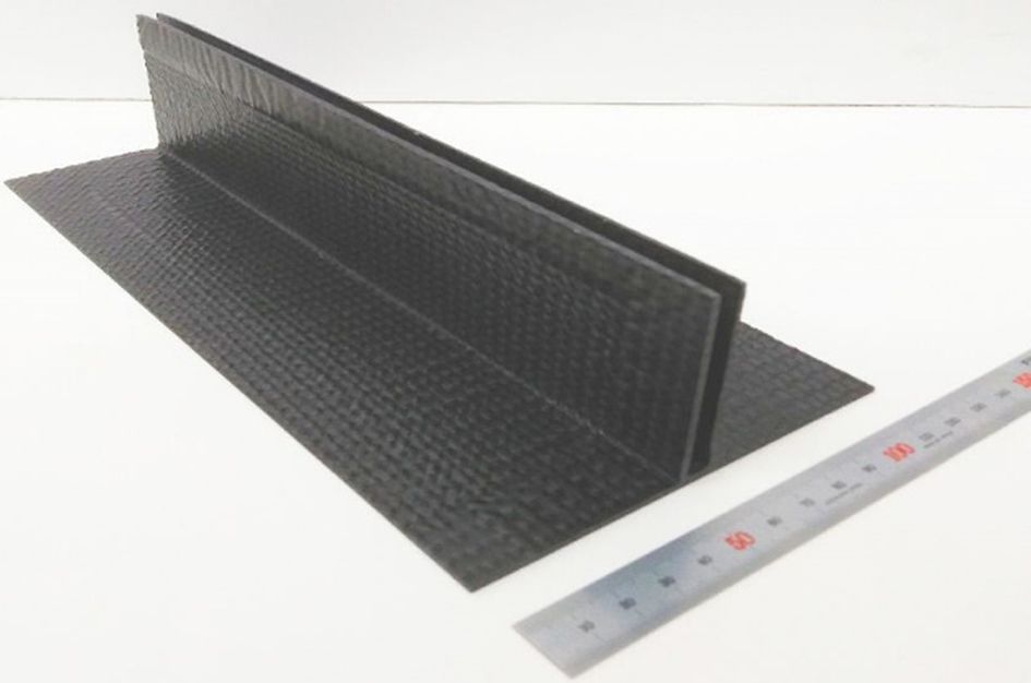
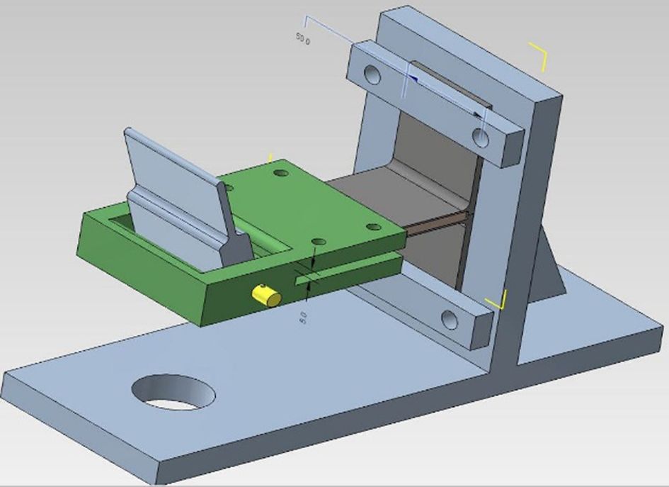
After the infusion, the beam is cut into the shape shown in Fig. 8 and later into smaller specimen with specific dimensions of depth of 50 mm, flange width of 120 mm, and a height of 100 mm, respectively, following the dimensions used for the T-joint pull-off-test [12]. A small 2D textile composite plate, with the dimensions 95 mm × 50 mm and 4 mm thickness, is inserted into the π-beam samples using adhesive LOCTITE EA 9695 AERO to form a strong bond and create a composite T-joint connection. Each T-joint is mounted on a base structure as shown in Fig. 9.
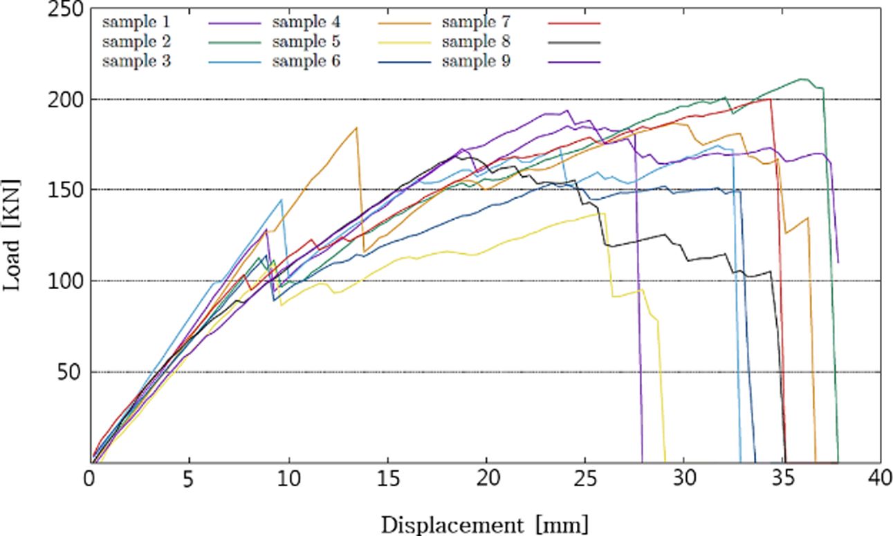
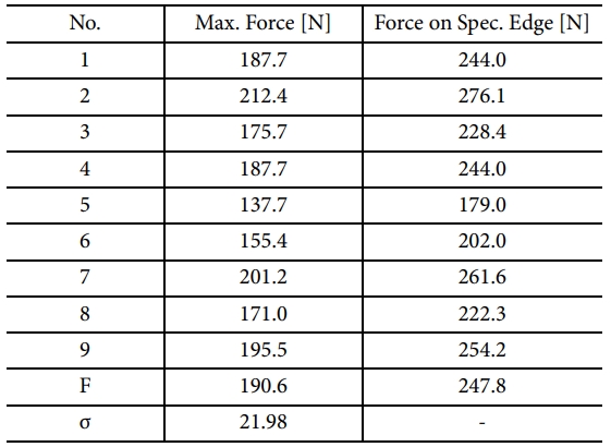
The T-joint is then inserted into a clamping device (green) with a hinge joint. The distance from the hinge joint to the bottom of the π-beam is 130 mm. The T-joint bending test is done on an Instron tensile testing machine with a testing speed of 2.5 mm/min. A linear-elastic behavior is observed in the load-displacement graph in Fig. 10 up to the displacement of 10 mm in most specimen. Then further displacement initiates cracks in the epoxy matrix and fractures of fibers leading to sudden drops of the force in the curve at around 8 mm to 13 mm displacement. After a non-linear elastic-plastic transition, the samples can take a higher load while several load drops occur during further displacement from 10 mm to 35 mm. In the displacement, range from 28 mm up to 38 mm the integrity of the connection is mostly lost while the resisting force of the composite is heading towards zero, emitting noise from the specimen. As a result, the maximum force that the nine specimen withstood ranged from 138 N to 212 N, yielding an average value of 190 N (Table 1).
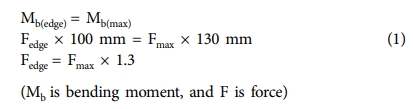
Therefore, the real average force on the specimen edge can be considered as 247.8 N, when calculated using bending moment.
|
Fig. 8 π-beam after infusion and cuttin |
|
Fig. 9 Clamp setup |
|
Fig. 10 T-joint bending test results |
Several 3D preform pattern being developed. After resin infusion and consolidation, samples of the preform are tested for mechanical properties such as interlaminar shear strength, compressive strength, and tensile strength. The composites of orthogonal weaving pattern show in general better mechanical properties than the other types of pattern. In the case of the tensile test in fill-yarn direction, the ORT pattern provides with a tensile strength of 950 MPa a 40% higher tensile strength than the LTL-pattern. In the ILS test, the ORT-pattern shows an ILS strength of 62 MPa, using a dense pattern combined of 12k warp and 12k fill yarn. Theπ-beam samples are woven and tested as part of a T-joint [13]. During a T-joint bending test an average force for the chosen geometry, of 190 N with a standard deviation of 22 N is observed. Further investigation is needed for 3D preforms using weaving machines considering limitations such as weaving loom width and complexity of the lifting diagram.
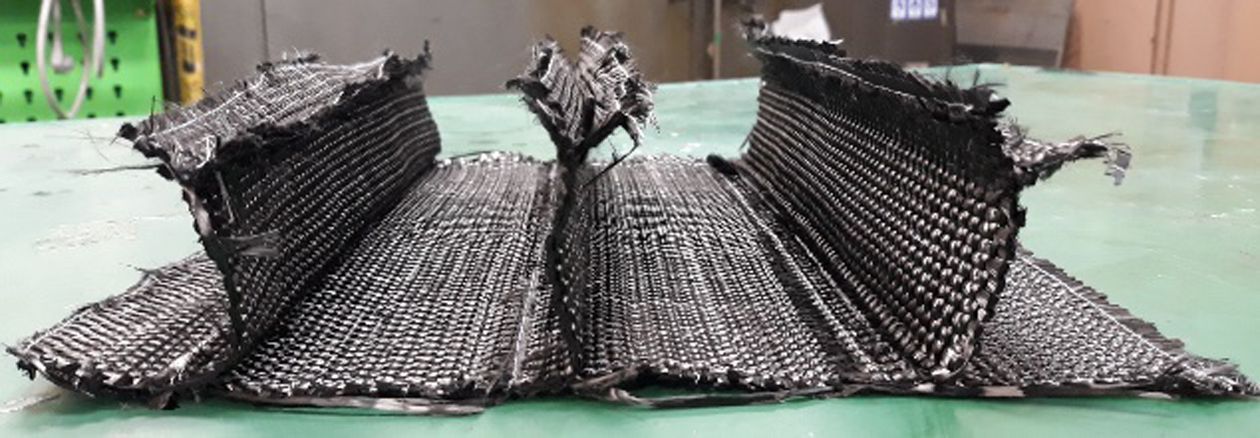
Besides, the usability of the elements as connectors or add-on parts should be examined. The production of a stiffening panel with integrated stringers could be achieved with the conventional weaving loom. Nevertheless, further development, improvement, and optimization of the woven preforms needs to be conducted. Fig. 11
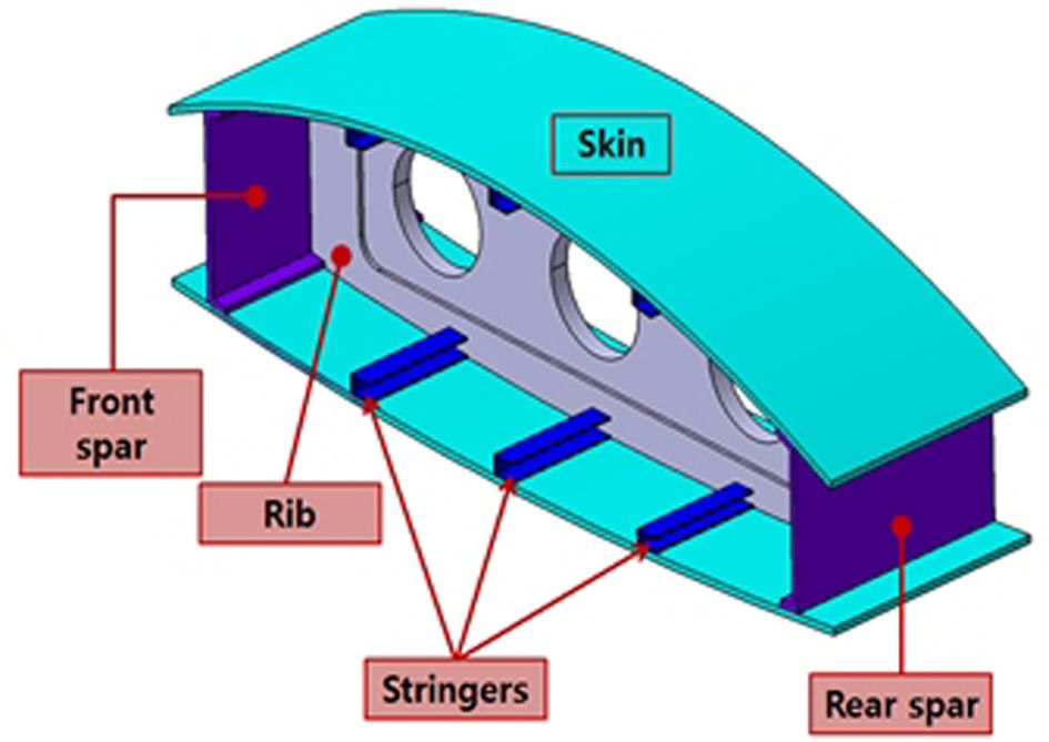
After manufacturing, a mechanical test should usually verify the mechanical properties of the whole application or segments of those. Based on the verified strength, the woven and infused beams or panels could be considered to be integrated into larger components e.g. a wing structure of a small airplane in Fig. 12, or as a shell element of a rotor blade [14]. In the end, the 3D weaving technique offers many possibilities for new applications and structures. Considering time and labor as the most cost-driven parameters in modern production, the 3D weaving technique offers a reduction of several manufacturing steps such as hand-lay up of textile layers and cutting and converting into preform shape. Therefore, the 3D- weaving technique could be an important processing method for a faster and more efficient composite production.
|
Fig. 11 Integrally woven stiffening panel with stringers |
|
Fig. 12 Wing part structure with stringer |
This research is financially supported by Changwon National University 2019~2020.
- 1. Kazemahvazi, S., Khokar, N., Hallstrom, S., Wadley, H.N.G., and Deshpande, V.S., “Confluent 3D-assembly of fibrous structures,” Composites Science and Technology, Vol. 127, 2016, pp. 95-105.
-

- 2. Ansar, M., Xinwei, W., and Chouwei, Z., “Modeling Strategies of 3D Woven Composites: A Review,” Composite Structures, Vol. 93, 2011, pp. 1947-1963.
-
- 3. Bilisik, K., “Multiaxis Three-dimensional Weaving for Composites: A Review,” Textile Research Journal, Vol. 82, 2012, pp. 725–743.
-
- 4. Mcclain, M., and Georings, J., “Overview of Recent Developments in 3D Structures,” Albany Engineered Composites, 2012, pp. 1–12.
- 5. Quan, Z., Wu, A., Keefe, M., Qin, X., Yu, J., Suhr, J., Byun, J.H., Kim, B.S., and Chou, T.W., “Additive Manufacturing of Multi-directional Preforms for Composites: Opportunities and Challenges,” Materials Today, Vol. 18, 2015, pp. 503–512.
-
- 6. N. Khokar, “3D-Weaving: Theory and Practice,” The Journal of The Textile Institute, Vol. 92, 2001, pp. 193-207.
-
- 7. Stig, F., and Hallström, S., “Assessment of the Mechanical Properties of a new 3D Woven Fibre Composite Material,” Composites Science and Technology, Vol. 69, 2009, pp. 1686–1692.
-
- 8. Jo, K., Klapper, V., Kim, H., Lee, J., Han, J., and Byun, J., “Manufacture of 3D Textile Preform and Study on Mechanical Properties of Composites,” The Korean Society for Composite Materials, Vol. 32, 2019, pp. 65–70.
-
- 9. Byun, J., Jo, K., and Klapper, V., “3D Textile Preform Manufacturing and Composites RTM Technology Development,” in Proceeding of The Society for Aerospace System Engineering, 2018, pp. 57–59.
- 10. Han, J.W., Lee, J.W., Park, J.W., and Kim, J.H., “The Study of Equipment System Upgrade for 3D Weaving,” in Proceeding of The Society for Aerospace System Engineering, 2018, pp. 60–61.
- 11. Lee, L., Rudov-Clark, S., Mouritz, A.P., Bannister, M.K., and Herszberg, I., “Effect of Weaving Damage on the Tensile Properties of Three-dimensional Woven Composites,” Composite Structures, Vol. 57, 2002, pp. 405–413.
-
- 12. Song, J., “Development of 3d Weaving Preform Beam Structure for Aircraft Wing Application,” Changwon, Korea, 2018.
- 13. Park, G., Lee, D., and Song, J., “Joint Design and Strength Analysis of Preform Beam Structure,” in Proceeding of The Society for Aerospace System Engineering, 2018, pp. 66–67.
- 14. Mouritz, A.P., Bannister, M.K., Falzon, P.J., and Leong, K.H., “Review of Applications for Advanced Three-dimensional Fibre Textile Composites,” Composites Part A: Applied Science and Manufacturing, Vol. 30, 1999, pp. 1445-1461.
-
 This Article
-
2021; 34(2): 96-100
Published on Apr 30, 2021
- 10.7234/composres.2021.34.2.096
- Received on Dec 8, 2020
- Revised on Feb 24, 2021
- Accepted on Mar 30, 2021
Services
- Abstract
1. introduction
2. weaving of π-beams
3. t-joint bending test
4. conclusion
- Acknowledgements
- References
- Full Text PDF
Shared
Correspondence to
- Chee-Ryong Joe
-
School of Mechanical Engineering, Changwon National University, Changwon, Korea
- E-mail: jcr@changwon.ac.kr
Gangnam Mirae Tower, Suite 601, 174 Saimdang-ro, Seocho-gu, Seoul 06627, South Korea
Tel: +82-2-598-1550 Fax: +82-2-598-1557 E-mail: composites@kscm.re.kr