


- Evaluation of Stamp Forming Process Parameters for CF/PEKK Thermoplastic Composite Using Finite Element Method
Keung-In Lee*, Hyeon-Seok Choe*, June-Woo Kwak*, Jun-Sung Lee*, Hyun-Woo Ju**, Jin-Hwe Kweon*† , Young-Woo Nam*†
* School of Mechanical and Aerospace Engineering, Gyeongsang National University
** Korea Aerospace Industries, Ltd.- 고속 열 성형 유한요소해석을 활용한 CF/PEKK 열가소성 복합재 구조물 제작 공정 예측 및 검증
이경인* · 최현석* · 곽준우* · 이준성* · 주현우** · 권진회*† · 남영우*†
This article is an open access article distributed under the terms of the Creative Commons Attribution Non-Commercial License (http://creativecommons.org/licenses/by-nc/4.0) which permits unrestricted non-commercial use, distribution, and reproduction in any medium, provided the original work is properly cited.
This study presented the evaluation of the stamp forming process for L-shape CF/PEKK thermoplastic composite using the finite element model. The formability of three different trimming allowances has been examined for representative product geometry. The results showed that those manufactured by high trimming allowance showed more excellent formability in those areas. Moreover, the effects of the trimming allowances on the stress, thickness, wrinkle distributions of thermoplastic composites fabricated with the stamp forming process were evaluated. The comparison of the simulation and experimental results for the thickness and wrinkle distributions proved the accuracy of the stamp forming model. The crystallinity of the composite was performed by differential scanning calorimetry (DSC). The void content of the composite was evaluated by matrix digestion. Then, the fabricated structure was characterized and achieved high quality in crystallinity and void content. Consequently, the presented FEM modeling shows excellent potential for application in the aircraft product design process. This pragmatic approach could efficiently offer a valuable solution for the thermoplastic composite manufacturing field
본 연구에서는 유한요소법(FEM)에 기반한 CF/PEKK 열가소성 복합재 고속 열 성형 해석을 수행하였고 제작 공정을 예측 및 검증하였다. 대표적인 L 형 구조물 모델에 대해 트리밍 여유에 따른 성형성을 응력, 두께, 주름 분포를 분석하였다. 그 결과, 블랭크의 트리밍 여유가 증가할수록 구조물의 성형성이 향상하는 것을 확인하였다. 특히 두께 및 주름 분포 측면에서 해석 모델과 실험 결과를 비교하여서 고속 열 성형 모델의 타당성을 검증하였다. 제작된 구조물은 시차 주사 열량 분석법 및 이미지 분석법을 통해 결정화도와 기공률이 측정되었다. 제작된 열가소성 구조물의 전 영역 기공률은 평균 0.75%, 결정화도는 약 21%로 항공기에 적용 가능한 수치로 평가되었다. 따라서 본 연구를 토대로 열가소성 복합재 고속 열 성형 공정에 대해 효과적인 예측이 가능할 것으로 판단된다.
Keywords: 열가소성 복합재(Thermoplastic composite), 고속 열 성형 공정(Stamp forming process), 성형 해석(Forming simulation), 결정화도(Crystallinity), 기공률(Void content)
섬유 강화 복합재는 우수한 기계적 특성으로 인하여 항공 우주 분야에 광범위하게 사용되고 있다[1-7]. 이러한 섬유 강화 복합재는 열가소성, 열경화성 복합재로 분류되는데, 열가소성 복합재는 열경화성 복합재보다 부식 및 피로 저항, 내 환경성, 프리프레그 보관성 등이 우수한 장점을 가진다[8-15]. 또한 열가소성 복합재는 탈 오토클레이브(Out of Autoclave) 공정과 자동화 공정의 적용이 가능하다[16-20]. 하지만 열가소성 복합재 구조물 제작은 높은 소재 비용과 기술적 요구사항이 요구되어 사용이 제한되어 왔으며, 이러한 문제를 해결하기 위한 연구들이 지속되고 있다[21-26].
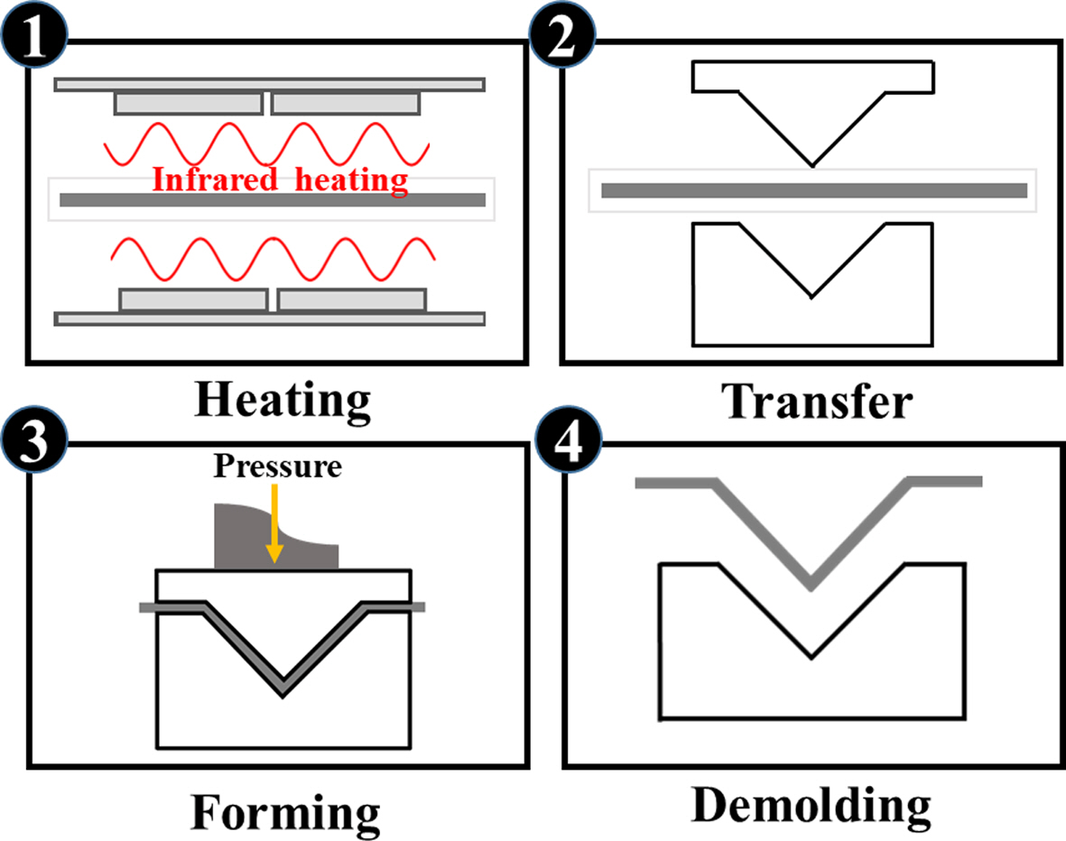
고속 열 성형 공정(Stamp forming)은 복잡한 형상의 복합재 성형이 가능한 압축 성형 계열의 공정이다[27]. 고속 열 성형 공정의 모식도는 Fig. 1에서 보인다. 비교적 짧은 공정 주기로 우수한 기계적 성능을 가지는 구조물을 만들 수 있기 때문에 고속 열 성형 공정은 열가소성 복합재 구조물을 자동화 공정으로 양산하는 데 가장 적합한 공정으로 주목받고 있다[28-31]. 이에 고속 열 성형 공정을 이용한 열가소성 복합재 성형에 대한 다양한 시도가 진행되고 있으나, 열가소성 수지의 높은 녹는점, 높은 점성은 열가소성 복합재 구조물 성형에 많은 제약을 끼친다[32-35]. 이로 인해 발생하는 금형 및 공정의 수정은 구조물 제작 비용과 시간을 매우 증가시켜 개발 기간 단축을 통한 공정 비용 절감이 요구된다[36-42].
최근, 컴퓨터 성능과 유한 요소법(FEM)의 발전으로 열가소성 복합재 고속 열 성형 공정 시뮬레이션이 가능해졌으며, 이를 통해 금형 제작 등 관련 초기 비용과 시간을 절감할 수 있게 되었다[43]. Jeon 등[44]은 요소수 탱크 외장품(Urea tank cover)를 대상으로 유한요소해석 기반 공정분석을 통해 개발공정을 수행하였다. 최종 설계된 형상과 공정을 스프링 백 해석을 통해 뒤틀림 변형을 확인하였다. Hannappel 등[45]은 CF/PEEK와 GF/PPS의 성형성을 조사하였다. 성형 시뮬레이션을 통해 주름 및 내부 층간 전단 패턴을 확인하였다. Vanclooster 등[46]은 FEM 시뮬레이션을 통해 반구형 몰드에서 성형된 GF/PPS 복합재의 섬유 방향 결정을 예측하고 draping 시뮬레이션을 갖는 데 있어 유리함을 확인하였다. Luke Mosse 등[47]은 섬유 금속 라미네이트(FML)성형의 유한요소 시뮬레이션을 통해 얻은 전단 응력 값과 lap shear 장치를 사용하여 얻은 전단 응력 특성 값이 유사함을 확인하였다. 기존에 수행되었던 연구들은 다양한 성형 해석 방법을 통해 시뮬레이션의 신뢰성을 향상시켰다. 하지만 고속 열 성형 공정을 통한 일 방향(Uni-direction) 섬유 구조물 제작에 관한 연구는 미흡한 상황이다.
본 연구에서는 상용 유한요소해석기반 고속 열 성형 해석을 통해 일 방향 섬유 열가소성 복합재 구조물의 공정을 예측하였다. 공정 설계는 금형의 구조와 공정변수를 고려하여 진행되었고, 성형 해석 모델과 동일한 형상과 공정을 가지는 구조물을 제작하여 성형해석 결과와 비교하였다. 그리고 시뮬레이션의 예측성을 검증하기 위해 두께 및 주름 발생을 분석하였다.
|
Fig. 1 Schematic diagram of the stamp forming progress |
2.1 고속 열 성형 해석
2.1.1 해석 조건
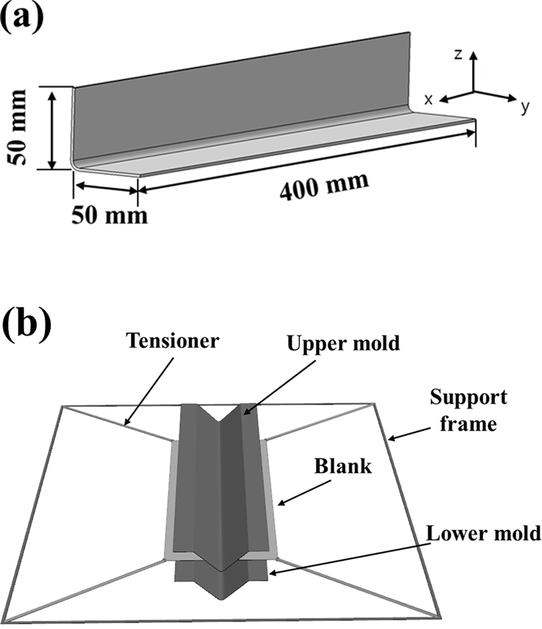
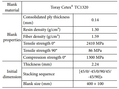
상용 유한요소해석 프로그램인 Aniform(ver. 3.6.3)을 이용하여 L-형상 구조물의 고속 열 성형 해석을 수행하였다. L-형상 구조물과 고속 열 성형 해석 유한요소 모델은 Fig. 2에 나타내었다. 유한요소 모델의 구성은 2D 요소인 trias 요소로 이루어져 있으며, 적절한 시간 증분(time step)의 설정을 위하여 블랭크의 격자 사이즈는 3 mm, 금형 격자 사이즈는 1 mm로 결정되었다. 블랭크에 장력을 적절히 유지하여 주름을 억제하도록 스프링 상수는 0.5 N/m, 스프링 초기하중은 15 N으로 입력하였다. 초기 금형 형상은 블랭크에 균일한 압력을 가할 수 있도록 설계하였다. 해석에서 금형의 열적 팽창은 고려되지 않으며, 금형으로부터 블랭크에 가해지는 압력의 크기는 21 bar이다[48]. 유한요소해석에 사용된 물성값은 Toray Cetex® TC1320AS4D PEKK의 라미네이트 물성값을 사용하였고, 기계적 물성값 및 초기 형상은 Table 1에 정리하였다[49].
2.1.2 블랭크 형상 설계
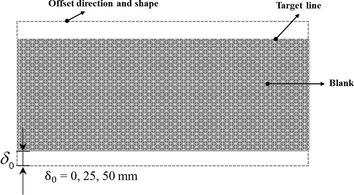
블랭크의 형상 설계는 다음 순서로 진행하였다. 우선 구조물 형상을 바탕으로 초기 블랭크 형상을 도출하고, 블랭크의 트리밍 여유를 결정하였다. 그리고 트리밍 여유에 따른 고속 열 성형 공정 영향을 분석하여 최종 형상이 결정되었다. 초기 블랭크 형상은 400 mm × 100 mm 직사각형 형상으로 정하였다. Fig. 3에서 나타낸 초기 블랭크는 설정된 블랭크의 외곽선을 나타낸 것이다. δ0의 값에 따라 트리밍 여유(δ0 = 0 mm, 25 mm, 50 mm)가 결정되며, 각각의 블랭크 형상으로 성형해석을 진행하였다.
2.2 고속 열 성형 해석 결과 및 고찰
2.2.1 응력 분포
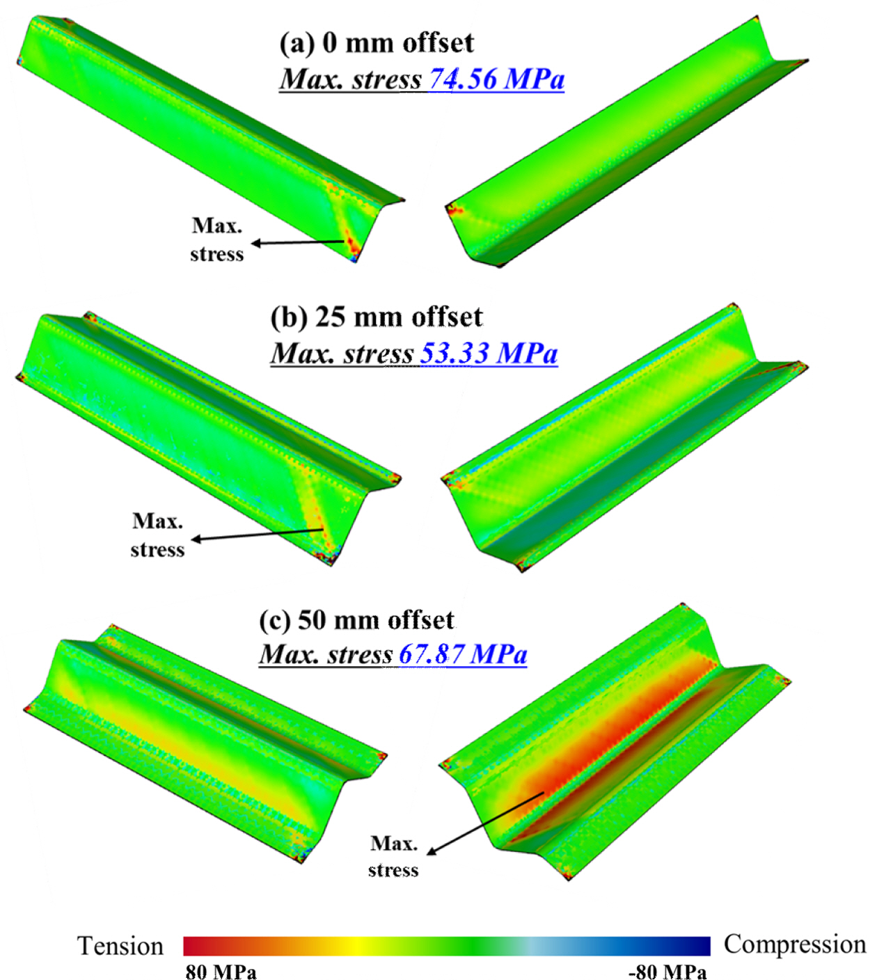
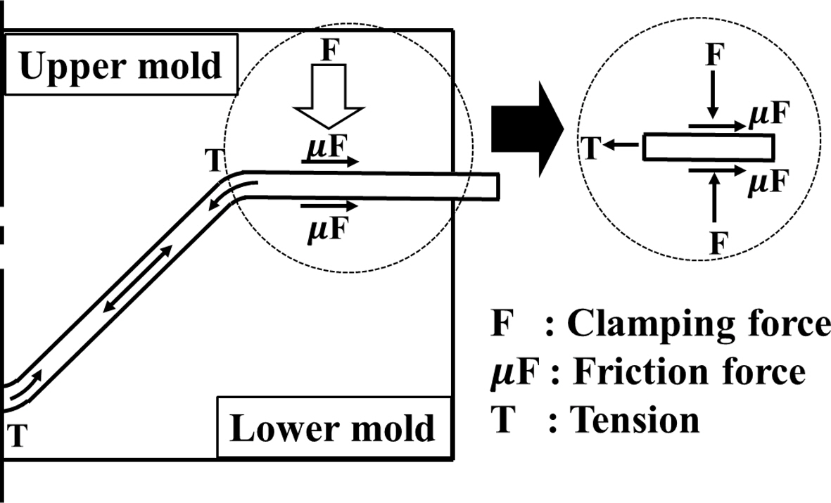
Fig. 4는 블랭크의 트리밍 여유 3가지 모델(δ0 = 0 mm, 25 mm, 50 mm)로 유한요소해석을 수행하여 고속 열 성형 공정 중 구조물에 가해지는 응력의 분포를 보여주고 있다. 해석 결과를 통해 δ0가 증가할수록 블랭크의 중심부 인장 응력은 증가하는 경향을 확인하였다. Case a, b는 구조물의 중심부에 응력이 발생하지 않았으나, Case c의 경우에는 높은 응력 분포가 나타났다. 이는 성형 작업 중 블랭크와 금형 사이의 마찰력에 의해 발생한 인장력이 영향을 끼친 것으로 분석되며 Fig. 5에 나타난다. 또한 접촉 면적이 클수록 더 많은 인장력이 발생함을 확인하였다. 반면 모든 경우에서 블랭크 그리퍼의 인근에서는 높은 응력이 발생한다는 것을 확인하였다. Case a, Case b에 비하여 높은 응력 집중이 보이며, Case b와 Case c에서도 유사한 경향이 확인되었다. 이는 텐셔너로 인해 블랭크에 가해지는 장력 방향과 공정 중 블랭크에 가해지는 압력의 방향이 영향을 미친 것으로 분석되며, 공정 중 불필요한 응력의 발생을 줄이기 위해서는 텐셔너에 의한 장력의 방향이 중요한 요인이라는 것을 확인하였다. 구조물에 충분한 트리밍 여유를 가지는 경우, 이러한 응력의 영향을 피할 수 있음을 확인할 수 있었다.
2.2.2 두께 증감도
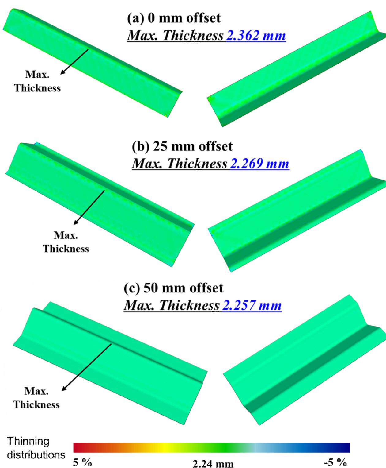
Fig. 6은 트리밍 여유 3가지 모델에 대한 L-형상 구조물의 두께 분포를 보여준다. 고속 열 성형 공정을 통해 성형된 모든 구조물에서 두께 편차 5% 내외의 균일한 두께 분포를 보이는 것을 확인하였다. δ0의 증가는 구조물 두께 분포의 편차를 줄이는 경향을 확인할 수 있다. 이를 통해 블랭크 내부에 가해지는 장력의 크기가 두께 증감에 한 요인으로 분석되며, 일정한 두께의 복합재를 제작하기 위해서는 트리밍 여유를 가져서 블랭크 내부의 장력 크기를 일정하게 유지하는 것이 중요하다고 판단된다.
2.2.3 주름 해석
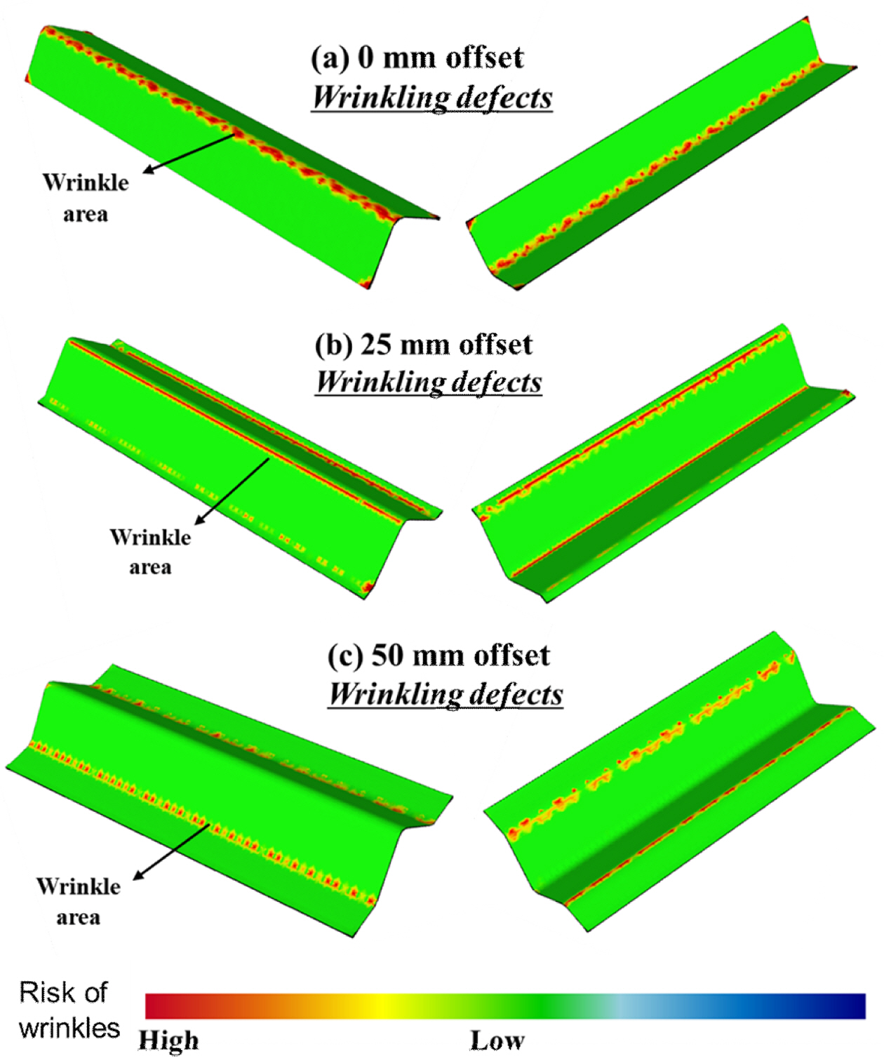
주름 해석은 유한요소해석 소프트웨어상에서 섬유의 압축 응력, 전단 응력, 두께, 굽힘 변형에 각각 1의 가중치를 두고 결과값을 평가하여 주름 발생 위험도를 알려준다. 해석 결과 모든 트리밍 여유 조건에서 곡면인 부분에 주름 확률이 높게 나타났다. Fig. 7에서와 같이 Case a, b의 경우 Case c와 달리 구조물 중심부 주름 위험도가 높게 확인되었다. 이것은 고속 열 성형 공정 중 복합재 내부에 충분한 장력이 형성되지 않아 구조물의 중심부에 주름이 발생하였다고 판단된다. Case c의 조건에서는 다른 조건들과 비교하여 주름 발생 영역이 성형 후 잘라내는 영역에서만 관찰된다. 따라서, δ0 = 50 mm의 조건에서 고속 열 성형 공정을 수행할 때 가장 우수한 성형성을 가진 구조물 제작이 가능하다고 판단하였다.
|
Fig. 2 (a) 3D model of L-shape clip and (b) finite element model for analysis |
|
Fig. 3 Determine offset line to make trimming allowance |
|
Fig. 4 Stamp forming analysis result for L-shape clip: x-direction stress; (a) δ0 = 0 mm, (b) δ0 = 25 mm, (c) δ0 = 50 mm |
|
Fig. 5 Tension forces acting on blank |
|
Fig. 6 tamp forming analysis result for L-shape clip: Thickness distributions; (a) δ0 = 0 mm, (b) δ0 = 25 mm, (c) δ0 = 50 mm |
|
Fig. 7 Stamp forming analysis result for L-shape clip: Risk of wrinkle; (a) δ0 = 0 mm, (b) δ0 = 25 mm, (c) δ0 = 50 mm |
3.1 고속 열 성형 실험
3.1.1 블랭크 및 금형 제작
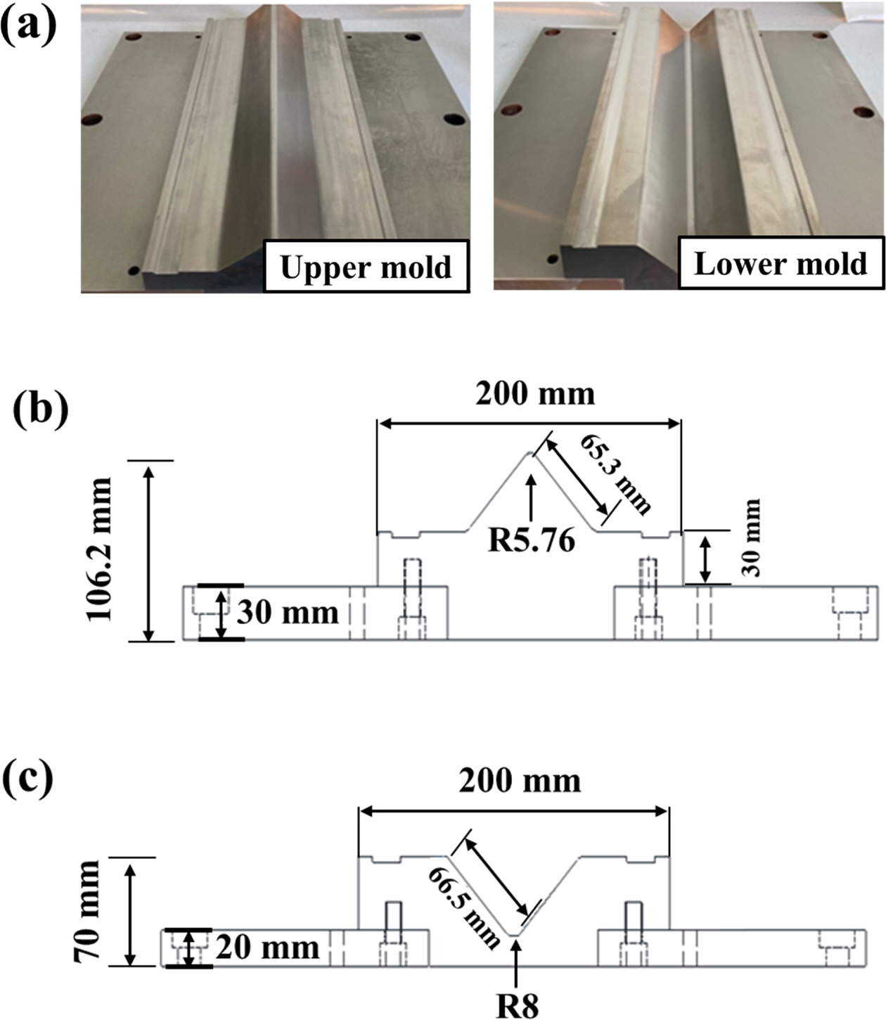
Hot press 공정을 통하여 CF/PEKK 라미네이트를 제작하였다. Toray Cetex® TC1320 AS4D PEKK를 [45/0/-45/0/90/45/-45/90]s의 적층 각도로 적층하여 라미네이트를 제작하였으며, 경화된 라미네이트의 평균 두께는 2.26 mm로 나타난다. 이후 복합재 성형 장비를 활용하여 트리밍 여유 50 mm의 블랭크 규격으로 가공하였다. 고속 열 성형 공정에 사용된 금형은 SKD11-Steel 소재로 제작되었으며, 금형의 형상은 Fig. 8에서 확인할 수 있다.
3.1.2 고속 열 성형 공정
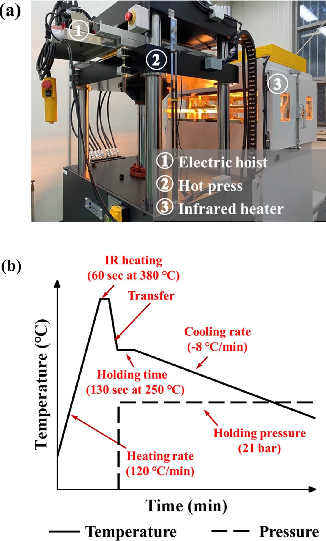
성형 해석 모델의 제작성을 검증하기 위해 해석과 동일한 공정으로 L-형상 구조물을 제작하였다. CF/PEKK 블랭크는 스프링 상수 0.5 N/m, 초기 하중 15 N을 가진 그리퍼를 통하여 네 모서리를 45o의 기울기로 고정하였다. 이는 IR heating 중 PEKK의 용융 온도인 337oC보다 높은 온도인 380oC에서 블랭크의 장력을 유지하여 성형 과정에서의 주름 생성을 방지하기 위해서다. 고속 열 성형 공정은 Fig. 9에 나타내었다. IR heater 내부에서 블랭크를 380oC까지 70oC/min의 승온률로 가열 후 1분간 유지하였다. 그 후 블랭크를 250oC로 예열된 금형으로 이송 후 21 bar의 압력으로 130초간 가압하였다. 이후 -8oC/min으로 냉각하며 구조물의 고형화를 수행하였다[48].
3.2 결과 및 고찰
3.2.1 성형성 예측 검증
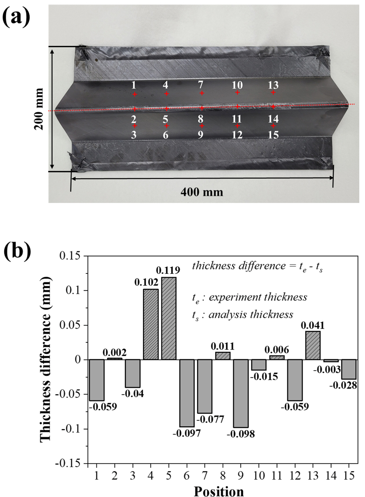
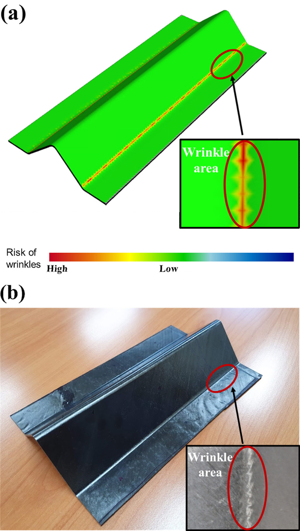
제작된 L-형상 구조물의 성형 품질을 평가하기 위해 두께 분포를 분석하였다. 구조물의 두께는 Fig. 10(a)와 같이 1부터 15까지 일정한 간격으로 선정하여 마이크로미터를 통해 측정하였다. 시뮬레이션과 실험의 두께 분포 차이는 5% 이내로 Fig. 10(b)에 나타내었다. L-형상 구조물의 중심 곡면부에 최고 두께는 2.358 mm로 나타났다. 측면 부분의 두께 차이는 4% 이내로 비교적 일정한 두께를 나타내었다. 주름의 경우 Fig. 11에서 보이는 것처럼 과도한 주름은 나타나지 않았다. 결과적으로 실험 결과는 시뮬레이션 결과와 잘 일치하며, L-형상 구조물의 고속 열 성형 해석 유한요소 모델은 실제 공정을 효과적으로 재현할 수 있다는 것을 입증한다. 특히 성형 후 불균일한 두께 분포와 주름 형성은 층간 분리로 발전 가능하며 이것은 제품의 구조 건전성에도 큰 영향을 미치기 때문에 고속 열 성형 해석 시 큰 주안점을 가져야 한다.
3.2.2 기공률 측정
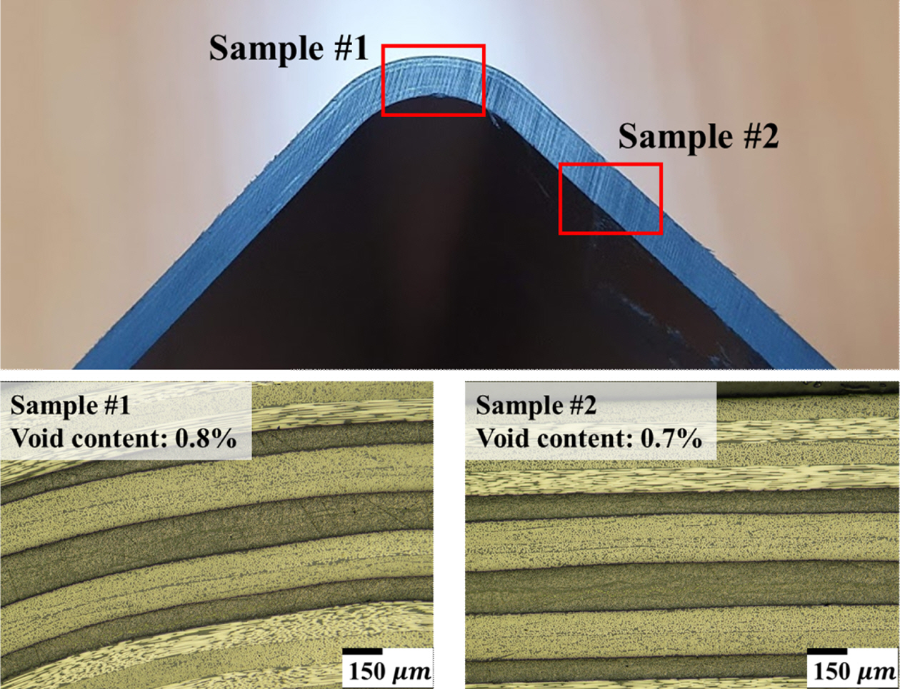
본 논문에서는 주사전자현미경을 통하여 구조물의 단면을 관찰하였으며, 이미지 분석법을 통하여 기공률을 나타내었다. 현미경을 이용한 고형화된 복합재의 단면 이미지 분석은 미시 구조적 관점에서 기공의 크기, 위치 및 모양을 확인하는 방법이다. Fig. 12는 고속 열 성형 공정을 통해 제작된 L형 클립의 형상이다. 이미지 분석은 CMEIAS-IT 이미지 분석 소프트웨어를 통하여 이미지 필터링 기능을 사용하였다. 이미지 분석 결과, Sample #1의 기공률은 0.8%, Sample #2의 기공률은 0.7%로 경화가 충분히 진행된 것을 확인하였다.
3.2.3 결정화도 측정
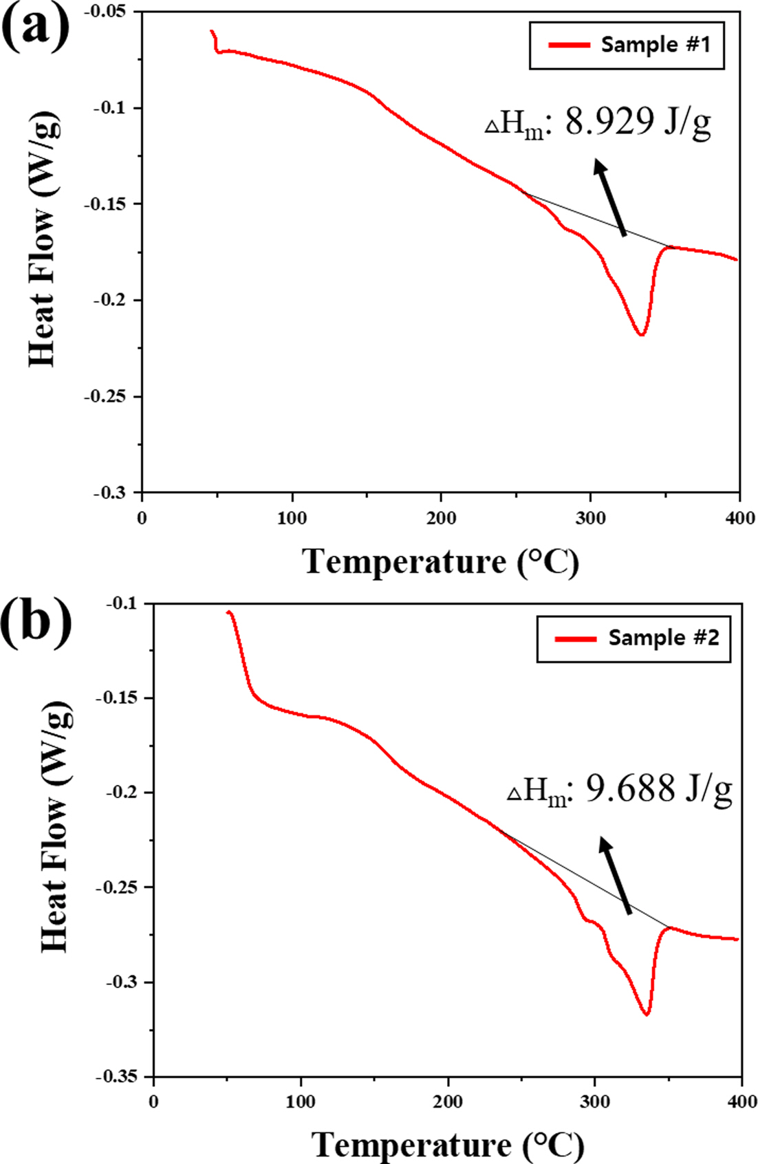
열가소성 복합재는 반-결정 구조로, 결정 구조의 정도에 따라서 재료의 기계적 특성에 영향을 주는 특성을 가진다. 본 연구에서는 CF/PEKK 복합재의 열적 거동을 분석하기 위해 ASTM D3418을 참조하여 시차 주사 열량 분석법을 수행하였다[50]. TA Instruments의 Q2000 장비를 사용하여 엔탈피 변화를 측정하였으며, 측정에는 5 mg 중량의 시료가 사용되었다. 10oC/min의 승온속도로 400oC까지 승온되었으며, 결정화도는 식 (1)을 통해 계산되었다. 식 (1)에서 ΔHm은 용융점에서의 융합 엔탈피, ΔHc는 결정화 온도에서 냉각 결정화 엔탈피를 나타낸다. 또한 ΔHf는 고분자 물질이 100% 결정을 이루었을 때 나타나는 흡열량으로 PEKK의 값은 130 J/g이다. a의 값은 복합재의 섬유 체적비를 나타내며, 용해법을 통해 계산된다. Fig. 13에서 보이는 것처럼 DSC 측정 중 냉각 결정화가 발생하지 않았으며, 제작된 구조물의 결정화도는 Sample #1은 20.2%, Sample #2는 21.92%로 소재의 최대 결정화도인 25%와 비교하였을 때 결정화가 충분히 이루어졌다고 판단된다.
|
Fig. 8 tail view on long clip mold: (a) prototype L-shape clip mold, (b) draft view of L-shape clip upper mold and (c) draft view of L-shape clip lower mold |
|
Fig. 9 (a) Stamp forming system and (b) stamp forming cycle |
|
Fig. 10 (a) Position of measuring points and (b) prototype Lshape clip |
|
Fig. 11 (a) Numerical wrinkle distribution within the L-shape clip and (b) experimental wrinkle distribution within the L-shape clip |
|
Fig. 12 Cross-sectional micrographs of L-shape clip |
|
Fig. 13 DSC data for (a) sample #1 and (b) sample #2 |
본 연구에서는 열가소성 복합재 L형 구조물에 대하여 상용 유한요소해석 프로그램인 Aniform을 이용하여 고속 열 성형 해석을 수행하였고, 실제 구조물을 제작하여 제작 공정을 검증하였다. 스프링 계수, Pre-load, 압력을 선정하고 시뮬레이션을 활용하여 0 mm, 25 mm, 50 mm의 블랭크의 트리밍 여유를 결정하였다. 트리밍 여유가 50 mm인 블랭크로 제작한 복합재의 경우 응력 분포, 두께 증감도, 주름 해석에서 우수한 성형성을 가지는 것을 확인하였다. 그리고 해석을 검증하기 위해 시뮬레이션으로 설계된 고속 열 성형 공정을 수행하여 구조물을 제작하였다. 제작된 구조물과 시뮬레이션 두께를 비교하였으며, 전 영역에서 오차율 5% 이하의 두께 차이를 보이는 것을 확인하였다. 또한 대부분의 영역에서 주름이 발생하지 않음에 따라 주름 예측 정밀도를 확인하였으며, 성형 예측 방법의 타당성을 확보하였다. 또한 현미경 분석, DSC 측정을 통하여 기공률과 결정화도를 측정하였다. 측정 결과 평균 기공률 0.75%, 평균 결정화도 21.06%로 항공기에 적용 가능한 수치로 평가되었다.
본 연구는 산업통상자원부의 재원으로 한국산업기술진흥원의 지원을 받아 수행한 2019년 해외수주연계 항공부품산업 공정기술개발 사업(P0010341_AFP와 OoA공정기술 기반 단일통로 대형민항기용 4 m 이상급 복합재 주익 스킨-스트링거 일체형 모듈 및 3 m 이상급 열가소성 복합재 동체 모듈 개발)의 지원을 받아 수행된 연구 결과입니다.
- 1. Henning, F., Kärger, L., Dörr, D., Schirmaier, F.J., Seuffert, J., and Bernath, A., “Fast Processing and Continuous Simulation of Automotive Structural Composite Components,” Composites Science and Technology, Vol. 171, 2019, pp. 261-279.
-

- 2. Lee, J.M., Lee, C.J., Kim, B.M., and Ko, D.C., “Design of Prepreg Compression Molding for Manufacturing of CFRTP B-pillar Reinforcement with Equivalent Mechanical Properties to Existing Steel Part,” International Journal of Precision Engineering and Manufacturing, Vol. 21, 2020, pp. 545-556.
-
- 3. Vieille, B., Albouy, W., Chevalier, L., and Taleb, L., “About the Influence of Stamping on Thermoplastic-based Composites for Aeronautical Applications,” Composites Part B: Engineering, Vol. 45, No. 1, 2013, pp. 821-834.
-
- 4. Suemasu, H., Friedrich, K., and Hou, M., “On Deformation of Woven Fabric- Reinforced Thermoplastic Composites During Stamp-forming,” Composites Manufacturing, Vol. 5, 1994, pp. 31-39.
-
- 5. Trudel-Boucher, D., Fisa, B., Denault, J., and Gagnon, P., “Experimental Investigation of Stamp Forming of Unconsolidated Commingled E-glass/polypropylene Fabrics,” Composites Science and Technology, Vol. 66, 2006, pp. 555-570.
-
- 6. Lebrun, G., Bureau, M.N., and Denault, J., “Thermoforming-Stamping of Continuous Glass Fiber/Polypropylene Composites: Interlaminar and Tool-Laminate Shear Properties,” Industrial Materials Institute, Journal of Thermoplastic Composite Materials, Vol. 17, 2004, pp. 137-165.
-
- 7. Ning, H., Vaidya, U., Janowski, G.M., and Husman, G., “Design, Manufacture and Analysis of a Thermoplastic Composite Frame Structure for Mass Transit,” Composite Structures, Vol. 80, 2007, pp. 105-116.
-
- 8. Gorczyca-Cole, J.L., Sherwood, J.A., and Chen, J., “A Friction Model for Thermostamping Commingled Glass-polypropylene Woven Fabrics,” Composites Part A: Applied Science and Manufacturing, Vol. 38, 2007, pp. 393-406.
-
- 9. Gorczyca, J., Shearwood, J., Liu, L., and Chen, J., “Modeling of Friction and Shear in Thermostamping of Composites - Part I,” Journal of Thermoplastic Composite Materials, Vol. 38, 2004, pp. 1911-1929.
-
- 10. Wakeman, M.D., Blanchard, P., and Manson, J.-A.E., “Void Evolution During Stamp Forming of Thermoplastic Composites,” 15th International Conference on Composite Materials, 2005.
- 11. Lessard, H., Lebrun, G., Benkaddour, A., and Pham, X.-T., “Influence of Process Parameters on the Thermostamping of a [0/90]12 Carbon/Polyether Ether Ketone Laminate,” Composites Part A: Applied Science and Manufacturing, Vol. 70, 2015, pp. 59-68.
-
- 12. Liu, L., Chen, J., Gorczyca, J., and Shearwood, J., “Friction and Shear in Thermostamping of Composites—Part II,” Journal of Thermoplastic Composite Materials, Vol. 38, 2004.
- 13. Mallick, P.K., “Thermoplastics and Thermoplastic-matrix Composites for Lightweight Automotive Structures,” Materials, Design and Manufacturing for Lightweight Vehicles (Second Edition), 2021, pp. 187-228.
-
- 14. Mathijsen, D., “The Black Magic of Carbon Fiber Reinforced Thermoplastics,” Reinforced Plastics, Vol. 59, No. 4, 2015, pp. 185-189.
-
- 15. Harrison, P., Gomes, R., and Curado-Correia, N., “Press Forming a 0/90 Cross-ply Advanced Thermoplastic Composite Using the Double-dome Benchmark Geometry,” Composites Part A: Applied Science and Manufacturing, Vol. 54, 2013, pp. 56-69.
-
- 16. Ten Thije, R.H.W., Akkerman, R., Ubbink, M., and van der Meer, L., “A Lubrication Approach to Friction in Thermoplastic Composites Forming Processes,” Composites Part A: Applied Science and Manufacturing, Vol. 42, 2011, pp. 950-960.
-
- 17. Hallander, P., Akermo, M., Mattei, C., Petersson, M., and Nyman, T., “An Experimental Study of Mechanisms Behind Wrinkle Development during Forming of Composite Laminates,” Composites Part A: Applied Science and Manufacturing, Vol. 50, 2013, pp. 54-64.
-
- 18. Slange, T.K., Warnet, L.L., Grouve, W.J.B., and Akkerman, R., “Influence of Prepreg Characteristics on Stamp Consolidation,” AIP Conference Proceedings, Vol. 1896, 2017, 030034.
-
- 19. Gabrion, X., Placet, V., Trivaudey, F., and Boubakar, L., “About the Thermomechanical Behaviour of a Carbon Fibre Reinforced High-temperature Thermoplastic Composite,” Composite B: Engineering, Vol. 95, 2016, pp. 386-394.
-
- 20. Schneeberger, C., Wong, J.C., and Ermanni, P., “Hybrid Bicomponent Fibres for Thermoplastic Composite Preforms,” Composite A: Applied Science and Manufacturing, Vol. 103, 2017, pp. 69-73.
-
- 21. Boisse, P., Hamila, N., and Madeo, A., “Modelling the Development of Defects During Composite Reinforcements and Prepreg Forming,” Philosophical Transactions Mathematical Physical and Engineering Sciences, Vol. 374, No. 2071, 2016, 20150269.
-
- 22. Kiran, G.B., Suman, K.N.S., Rao, N.M., and Rao, R.U.M., “A Study on the Influence of Hot Press Forming Process Parameters on Mechanical Properties of Green Composites Using Taguchi Experimental Design,” International Journal of Engineering, Science and Technology, Vol. 3, 2011, pp. 253-263.
-
- 23. Benkaddour, A., Lebrun, G., and Laberge-Lebel, L., “Thermostamping of [0/90]n Carbon/Peek Laminates:Influence of Support Configuration and Demolding Temperature on Part Consolidation,” Polymer Composites, Vol. 39, 2018, pp. 3341-3352.
-
- 24. Behrens, B.A., Raatz, A., Hübner, S., Bonk, C., Bohne, F., Bruns, C., and Micke-Camuz, M., “Automated Stamp Forming of Continuous Fiber Reinforced Thermoplastics for Complex Shell Geometries,” Procedia CIRP, Vol. 66, 2017, pp. 113-118.
-
- 25. Balakrishnan, V.S., Obrosov, A., Kuke, F., Seidlitz, H., and Weiß, S., “Influence of Metal Surface Preparation on the Flexural Strength and Impact Damage Behaviour of Thermoplastic FRP Reinforced Metal Laminate Made by Press Forming,” Composites Part B: Engineering, Vol. 173, 2019, 106883.
-
- 26. Donadei, V., Lionetto, F., Wielandt, M., Offringa, A., and Maffezzoli, A., “Effects of Blank Quality on Press-Formed PEKK/Carbon Composite Parts,” Matrials, Vol. 11, 2018, 1063.
-
- 27. Xiong, H., Hamila, N., and Boisse, P., “Consolidation Modeling during Thermoforming of Thermoplastic Composite Prepregs Hu,” Matrials, Vol. 12, No. 18, 2019, pp. 2853.
-
- 28. Gong, Y., Song, Z., Ning, H., Hu, N., Peng, X., Wu, X., Zou, R., Liu, F., Weng, S., and Liu, Q., “A Comprehensive Review of Characterization and Simulation Methods for Thermo-stamping of 2D Woven Fabric Reinforced Thermoplastics,” Composites Part B: Engineering, Vol. 203, 2020, 108462.
-
- 29. Behrens, B.A., Hübner, S., and Neumann, A., “Forming Sheets of Metal and Fibre-reinforced Plastics to Hybrid Parts in One Deep Drawing Process,” Procedia Engineering, Vol. 81, 2014, pp. 1608-1613.
-
- 30. Vieille, B., Albouy, W., and Taleb, L., “Investigations on Stamping of C/PEEK Laminates: Influence on Meso-structure and Macroscopic Mechanical Properties under Severe Environmental Conditions,” Composites Part B: Engineering, Vol. 63, 2014, pp. 101-110.
-
- 31. Hwang, S.F., and Hwang, K.J., “Stamp Forming of Locally Heated Thermoplastic Composites,” Composites Part A: Applied Science and Manufacturing, Vol. 33, 2002, pp. 669-676.
-
- 32. Fernández, I., Blas, F., and Frövel, M., “Autoclave Forming of Thermoplastic Composite Parts,” Journal of Materials Processing Technology, Vol. 143-144, 2003, pp. 266-269.
-
- 33. Abbassi, F., Elfaleh, I., Mistou, S., Zghal, A., Fazzini, M., and Djilali, T., “Experimental and Numerical Investigations of a Thermoplastic Composite (carbon/PPS) Thermoforming,” Structural Control Health Monitoring, Vol. 18, 2011, pp. 769-780.
-
- 34. Guzman-Maldonado, E., Wang, P., Hamila, N., and Boisse, P., “Experimental and Numerical Analysis of Wrinkling during Forming of Multi-layered Textile Composites,” Composite Structures, Vol. 208, 2019, pp. 213-223.
-
- 35. Kim, D.J., Yu, M.H., Lim, J.Y., Nam, B.G., and Kim, H.S., “Prediction of the Mechanical Behavior of Fiber-reinforced Composite Structure Considering Its Shear Angle Distribution Generated during Thermo-compression Molding Process,” Composite Structures, Vol. 220, 2019, pp. 441-450.
-
- 36. Donderwinkel, T.G., Rietman, B., Haanappel, S.P., and Akkerman, R., “Stamp Forming Optimization for Formability and Crystallinity,” AIP Conference Proceedings, Vol. 1769, 2016, 170029.
-
- 37. Montazerian, H., Sourki, R., Ramezankhani, M., Rashidi, A., Koerber, M., and Milani, A.S., “Digital Twining of an Automated Fabric Draping Process for Industry 4.0 Applications: Part Imulti-body Simulation and Finite Element Modeling,” CAMX2019, 2019, pp. 1-10.
- 38. Chen, Q., Boisse, P., Park, C.H., Saouab, A., and Bréard, J., “Intra/inter-ply Shear Behaviors of Continuous Fiber Reinforced Thermoplastic Composites in Thermoforming Processes,” Composite Structures, Vol. 93, 2011, pp. 1692-1703.
-
- 39. Allaoui, S., Boisse, P., Chatel, S., Hamila, N., Hivet, G., Soulat, D., Vidal-Salle, E., “Experimental and Numerical Analyses of Textile Reinforcement Forming of a Tetrahedral Shape,” Composites Part A: Applied Science and Manufacturing, Vol. 42, 2011, pp. 612-622.
-
- 40. Wolthuizen, D.J., Schuurman, J., and Akkerman, R., “Forming Limits of Thermoplastic Composites,” Key Engineering Materials, Vol. 611-612, 2014, pp. 407-414.
-
- 41. Slange, T.K., Grouve, W.J.B., Warnet, L.L., Wijskamp, S., and Akkerman, R., “Towards the Combination of Automated Lay-up and Stamp Forming for Consolidation of Tailored Composite Components,” Composites Part A: Applied Science and Manufacturing, Vol. 119, 2019, pp. 165-175.
-
- 42. McCool, R., Murphy, A., Wilson, R., Jiang, Z., Price, M., Butterfield, J., and Hornsby, P., “Thermoforming Carbon Fibre-reinforced Thermoplastic Composites,” Journal of Materials: Design & Applications, Vol. 226, 2012, pp. 91-102.
-
- 43. Slange, T.K., Warnet, L., Grouve, W.J.B., and Akkerman, R., “Influence of Preconsolidation on Consolidation Quality After Stamp Forming of C/PEEK Composites,” AIP Conference Proceedings, Vol. 1769, 2016, 170022.
-
- 44. Jeon, Y.J., Heo, Y.M., Yun, S.H., and Kim, D.E., “Stamping Process Design to Develop a Urea Tank Cover for Excavators Based on Sheet Metal Forming Analysis,” Journal of Korea Society of Die & Mold Engineering, Vol. 14, 2020, pp. 49-55.
- 45. Haanappel, S.P., Ten Thije, R.H.W., Sachs, U., Rietman, B., and Akkerman, R., “Formability Analyses of Uni-directional and Textile Reinforced Thermoplastics,” Composites Part A: Applied Science and Manufacturing, Vol. 56, 2014, pp. 80-92.
-
- 46. Vanclooster, K., Lomov, S.V., and Verpoest, I., “Experimental Validation of Forming Simulations of Fabric Reinforced Polymers Using an Unsymmetrical Mould Configuration,” Composites Part A: Applied Science and Manufacturing, Vol. 40, 2009, pp. 530-539.
-
- 47. Lee, J.S., Hong, S.J., Yu, W.R., and Kang, T.J., “The Effect of Blank Holder Force on the Stamp Forming Behavior of Non-crimp Fabric with a Chain Stitch,” Composites Science and Technology, Vol. 67, 2007, pp. 357-366.
-
- 48. TORAY Cetex, “Stamp Forming Processing Guide,” TORAY Cetex, USA, 2019.
- 49. Aniform, Toray Cetex® TC1320 AS4D/PEKK Material Card, the netherlands, 2019.
- 50. ASTM D3418. Standard Test Method for Transition Temperatures of Polymers by Differential Scanning Calorimetry.
 This Article
-
2021; 34(5): 296-304
Published on Oct 31, 2021
- 10.7234/composres.2021.34.5.296
- Received on Sep 3, 2021
- Accepted on Sep 30, 2021
Services
Shared
Correspondence to
- Jin-Hwe Kweon, Young-Woo Nam
-
School of Mechanical and Aerospace Engineering, Gyeongsang National University
- E-mail: jhkweon@gnu.ac.kr, ywnam@gnu.ac.kr
Gangnam Mirae Tower, Suite 601, 174 Saimdang-ro, Seocho-gu, Seoul 06627, South Korea
Tel: +82-2-598-1550 Fax: +82-2-598-1557 E-mail: composites@kscm.re.kr