


- Facile Electrodeposition Technique for the Fabrication of MoP Cathode for Supercapacitor Application
Prakas Samanta*, **, Souvik Ghosh*, **, Naresh Chandra Murmu*, **, Joong Hee Lee***† , Tapas Kuila*, **†
* Surface Engineering & Tribology Division, Council of Scientific and Industrial Research-Central Mechanical Engineering Research Institute, Durgapur-713209, India
** Academy of Scientific and Innovative Research (AcSIR), CSIR- Human Resource Development Centre, (CSIR-HRDC) Campus, Postal Staff College Area, Sector 19, Kamla Nehru Nagar, Ghaziabad- 201002, Uttar Pradesh, India
*** Department of Nano Convergence Engineering, Jeonbuk National University, Jeonju 54896, KoreaThis article is an open access article distributed under the terms of the Creative Commons Attribution Non-Commercial License (http://creativecommons.org/licenses/by-nc/4.0) which permits unrestricted non-commercial use, distribution, and reproduction in any medium, provided the original work is properly cited.
The continued environmental pollution caused by fossil fuel consumption has prompted researchers around the world to develop environmentally friendly energy technologies. Electrochemical energy storage is the significant area of research in this development process, and the research significance of supercapacitors in this field is increasing. Herein, a simple electrodeposition synthetic route was explored to develop the MoP layered cathode material. The layered structure provided a highly ion-accessible surface for smooth and faster ion adsorption/desorption. After Fe was doped into MoP, the morphology of MoP changes and the electrochemical performance was significantly improved. Specific capacitance value of the binder-free FeMoP electrode was found to be 269 F g-1 at 2 A g-1 current density in 6 M aqueous KOH electrolyte. After adding Fe to MoP, an additional redox contribution was observed in the redox conversion from Fe3+ to Fe2+ redox pair, and the charge transfer kinetics of MoP was effectively improved. This research can provide guidance for the development of supercapacitor electrode materials through simple electrodeposition technology.
Keywords: MoP, Supercapacitor, Electrochemistry, Electrodeposition
With the modernization of global technology development, energy consumption is increasing, causing the exhaustion of fossil fuel reservoir and degradation of the environment. Therefore, development of a highly efficient renewable energy storage and conversion system is exceedingly desirable in modern civilization to alleviate the future energy crisis [1]. Rechargeable batteries, supercapacitors (SC), fuel cells, and water electrolyzers are becoming important renewable energy harvesting and storage units. In the prior art, SCs have the attractive characteristics of long life, energy and power density compared to the batteries. Therefore, SCs are considered as the most promising energy storage devices [2]. Due to the high energy requirements of automobiles, portable electronics, electric vehicles, defense, aerospace and other fields, the energy performance of SCs needs to be improved.
SCs can store charge by two mechanism; pseudocapacitor and electrochemical double layer capacitor [3]. Redox-active metal oxides, sulfides, phosphide, nitrides, polymers etc. are used as cathode material in pseudocapacitor and conducting carbonaceous materials are generally used in electrochemical double layer capacitor [4]. The pseudocapacitors store charge via redox reaction and electrostatic adsorption/desorption takes place in electrochemical double layer capacitor. Different types of metal oxide, sulfide, phosphideetc are widely studied as the SCs cathode materials [4-6]. In particular, metal phosphides are extremely attractive due to their low resistive nature (consisting of free electron), high specific surface area, unique structure, and high theoretical capacity [7]. Shao et al. synthesized hierarchical 3D NixCo1-xO/NiyCo2-yP@C through phosphorization technique [8]. The resulting 3D structures exhibited excellent stability of ~84% capacity retention after 3000 cycles and showed outstanding 2638 F g-1 capacitance at 1 A g-1 current density [8]. Similarly, Kong et al. proposed conductive NiCoP nanoarray on Ni-foam as binder free SC electrode material followed by hydrothermal and annealing process [9]. The cathode material exhibited 9.2 F/cm-2 specific capacitance at 2 mA/cm-2 current density [9]. Hu et al. prepared high electrical conductive CoP via solid-state synthesis route by varying the annealing temperature and elucidated their electrochemical performance in 6M KOH electrolyte [10]. Wang et al. synthesized Ni-P by a facile solvothermal process and analyzed as pseudocapacitance properties in alkaline electrolyte. The NiP cathode exhibits 71.4% capacitance retention after 1000 cycles and displayed 1597 F g-1 specific capacitance at 0.5 A g-1 current density [11].
Recently, MoP cathode materials have gain significant attention towards the energy storage technology owing to their high theoretical capacity (632 mAh g-1), high electrical conductivity [12]. Due to the larger size of the P atom, the MoP crystal has obtained a nine-fold tetrakaidecahedral coordination sphere which results an active corners and edge [12,13]. Based on the above merits, Tian et al. have developed MoP/MnO2/CNT composite for the SC application through microwave irritation and define the electrochemical performance of the electrode in 6M KOH alkaline electrolyte [14]. The composite electrode exhibited ~447.6 F g-1 specific capacitance at 1 A g-1 and maintain 86.5% initial capacitance after 10000 cycles [14]. Jin et al. used MoP to stabilize Mo oxide nanotube for SC application which can exhibit high electrochemical stability in acidic medium [15]. Zong et al. proposed MoP@N-doped carbon nanosheets potassium ion hybrid capacitor. The cathode materials displays long term cycling stability 89.9% capacity retention after 800 cycles and 256.1 mA h g-1capacity at 0.1 A g-1 current density [16].
This work is focused on the development of Fe-doped MoP cathode material for SC applications. A facile electrodeposition technique was employed for the deposition of FeMoP material over nickel foam. A layered structured was obtained for FeMoP electrode materials which was beneficial for faster ion movement and smooth ion adsorption/desorption. The binder free FeMoP electrode exhibited 269 F g-1 specific capacitance at 0.2 A g-1 current density in 6M KOH electrolyte which was higher than MoP electrode. This finding suggested that an additional redox contribution was observed for FeMoP electrode from the redox conversion of Fe3+ to Fe2+ redox couple. The Fe incorporation into MoP enhances the electrical conductivity, resulting low charge transfer resistance.
2.1 Materials
Molybdenumchloride (MoCl5), Iron chloride (FeCl2), disodium phosphate (Na2HPO4) potassium hydroxide (KOH) and potassium chloride (KCl) were purchased from Sigma Aldrich, India. All the chemicals are of analytical grade and used as received without further purification. Nickel foam (NF) was obtained from Shanghai Winfrey New Material Co., Ltd., Sanghai, China. De-ionized (DI) water was used for all experimental procedure.
2.2 Preparation of Fe-doped MoP
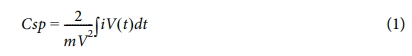
The Fe-doped MoP cathode was prepared by a facile electrodeposition route in three-electrode set-up. The NF was washed with water, ethanol and acetone mixed solution. The platinum mesh, Ag/AgCl and washed NF were used as counter, reference and working electrode, respectively in three-electrode set-up (schematic representation was demonstrated in Fig. 1(a)). About 300 mg of MoCl5 and 3 mg of FeCl2 was dissolved in 80 ml DI water and stirred for 15 min. Then, 200 mg of Na2HPO4 and 100 mg KCl were added to the aforementioned solution under constant stirring for 10 min. The resultant aqueous solution was used as electrolyte for Fe-doped MoP electrodeposition. The chronoamperometry process at fixed potential ~ -1.2 V was maintained for 10 min. After performing the electrodeposition process, the NF was dried at vacuum oven at 80oC for overnight and directly used for electrochemical analysis. The MoP was electrodeposited over NF by following similar procedure except Fe precursor.
2.3 Physical characterization
Rigaku X-ray powder diffractometer was used to record the powder X-ray diffraction (PXRD) pattern of the samples. Sigma HD (Carl Zeiss, Germany) field-emission scanning electron microscopy (FE-SEM) was used to record the surface morphology of the samples.
2.4 Electrochemical characterization
The PARSTAT 3000 electrochemical work station (Princeton Applied Research, USA) was used to record the electrochemical performance. The 6M KOH electrolyte was used for electrochemical test. The electrodeposited NF was used as working electrode. The platinum mesh and Ag/AgCl were used as counter and reference, respectively in three-electrode set-up. The galvanostatic charge/discharge (GCD) at 2, 3, 5, 7, and 10 A g-1 current densities, potentiostatic cyclic voltammetry (CV) at 10, 30, 50, 70 and 100 mV s-1 scan rates and electrochemical impedance spectroscopy (EIS) tests were recorded in between 0.1 Hz to 1 MHz. ZView (3.5f) software was used to fit the Nyquist plot. The specific capacitance (Csp) of the electrode was determined by using following equation:
Where, dt is the discharge time of the GCD curve, m (gm) is the loaded mass of synthesized material, dV (V) is the working potential window and I (A) represents the constant GCD current.
|
Fig. 1 Schematic of the electrodeposition processes (a), PXRD pattern of MoP and FeMoP material |
3.1 Physicochemical characterization
The XRD pattern of the electrode materials were recorded as demonstrated in Fig. 1(b). The characteristic diffraction peaks situated at 27.8, 31.39, 42.8, 56.9, 57.2, 64.6, 67.1, 67.8, and 74.3o were correspondence to the (001), (100), (101), (110), (002), (111), (200), (102) and (201) planes, respectively (JCPDS No.- 65-6487) [12,14,15]. Appearance of sharp and broad peaks indicated an amorphous crystalline structure was formed which beneficial for faster ion movement. In addition, a small peak at 12.2o was attributed to the MoO3 crystal phase [14]. Interestingly, after doping Fe into the MoP crystal phase, the peak was observed to shift to a lower angle. This finding indicated that the lattice spacing of the MoP lattice was increased which improved ion insertion/de-insertion mechanism during the charge/discharge process [17].
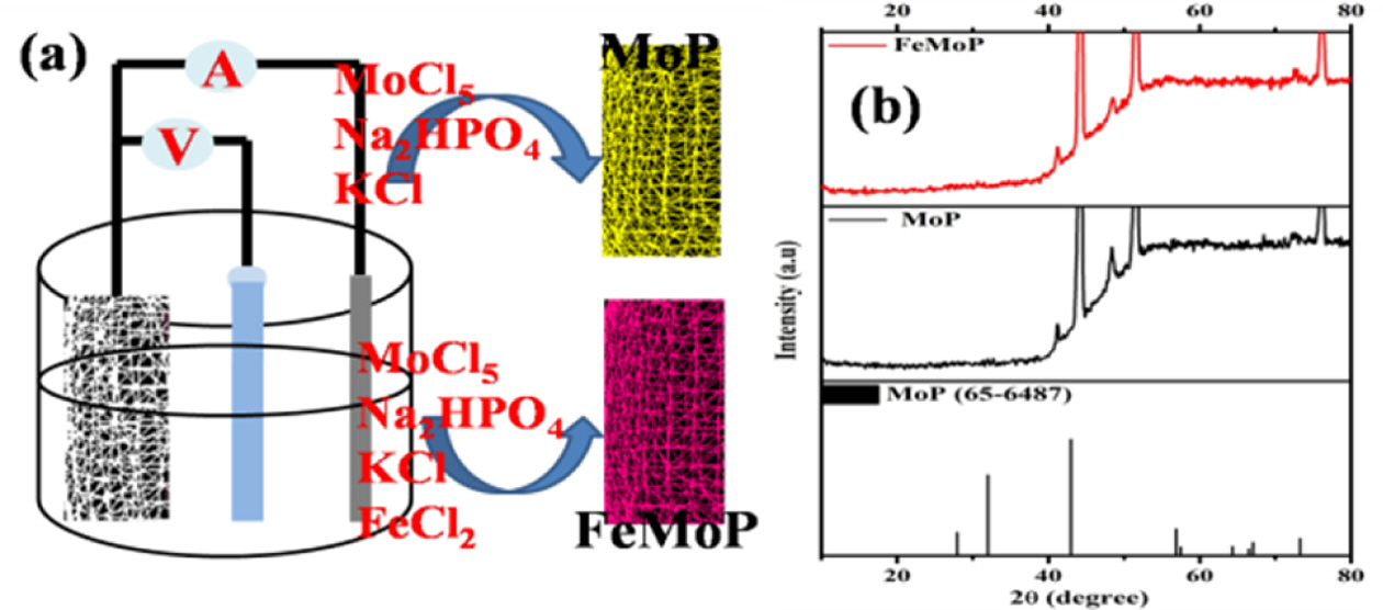
The FE-SEM images of the developed materials are shown in Fig. 2. The MoP material deposited over NF posseses a unique flake like architecture (Fig. 2(b)). An interconnected framework of ultrathin MoP sheet was observed at higher magnification (Fig. 2(b)). The MoP sheets were stacked layer by layer during the Fe doping and formed a 3D porous architecture (Fig. 2(c-d)). This kind of architecture provides higher active surface area, resulting to improve charge storage performance [1,17].
3.2 Electrochemical properties
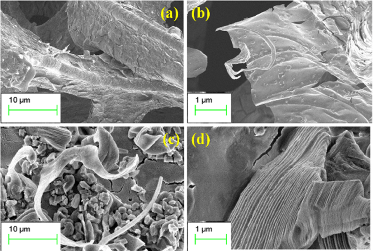
The electrochemical properties of the prepared material were performed using 3-electrode setup in 6M KOH electrolyte. Fig. 3(a-b) represents the CV curve of the MoP and Fe-MoP electrode material within -0.1 to 0.4 V (vs Ag/AgCl) potential ranges at 10, 30, 50, 70, 100 mV s-1 scan rates. Characteristic four redox peaks were present for both electrode at 0.23 & 0.27 V and 0.203 & 0.12 V at 10 mV s-1 scan rate, indicating the pseudocapacitive behavior of MoP electrode [14-16]. The cathode and anode peaks move towards negative and positive potentials region, respectively with increasing the scan rate from 10 to 100 mV s-1. This finding suggested that the electrode materials showed quasi-reversible behavior which was governed by the alkaline anion of electrolyte [1-3]. In addition, the peak current response increases with increasing the scan rate suggesting the faster redox kinetics and conforms the Ohm’s law. Furthermore, the anodic and cathodic current linear relationship was observed for both electrode which signifies that the redox conversion was controlled by the diffusion process [1,2,14-16]. As the scan rate increases, the time for ion diffusion becomes less and less. Therefore, the intensity of the redox peak at ~0.27 V is slowly reduced. It was evident that the current response of Fe-doped MoP was higher compared to the bared MoP electrode. This result suggested that an additional redox contribution was observed for FeMoP electrode from the redox conversion of Fe3+ to Fe2+ redox couple.
GCD of the electrode materials was carried out in the potential range of 0 to 0.4 V at various current densities (2 to 10 A g-1) using three-electrode set-up in 6M KOH electrolyte (Fig. 3(c-d)). The characteristic GCD curve associated with MoP and FeMoP electrode materials is consistent with the redox peak observed in the CV curve. Specific capacitance values of the MoP and FeMoP are 161 and 269 F g-1 at 2 A g-1 current density, respectively. It is found that the specific capacitance values decreased with increasing the current density due to the non-accessibility of the active electrode surface at higher current density [1-3,14,15]. The FeMoP electrode showed higher specific capacitance compared to MoP electrode with higher discharge time. This result demonstrated that the Fe doping can effectively improve the specific capacitance due to the addition Faradaic contribution.
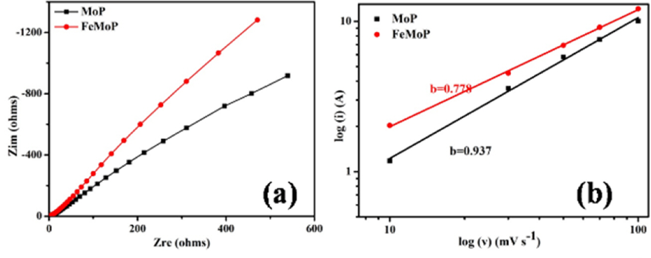
The EIS of the electrode material was carried out in the frequency range of 0.1 Hz to 1 MHz. Fig. 4(a) showed the Nyquist plot of the electrode material that showing the imaginary and real component of the impedance. Appearance of semicircle part at high-frequency region and straight line at low-frequency region are the general observation in the Nyquist diagram of a SC electrode material. The semi-circle provides resistance properties of the electrode material and electrode/electrolyte interface [1-3,17]. The charge transfer resistance characteristic of the electrode can be calculated from the semicircle of the Nyquist diagramas displayed in Fig. 4(a). It was evident that the FeMoP electrode showed lower charge transfer resistance compared to the MoP electrode suggesting incorporation of Fe into the MoP electrode enhanced the electrical conductivity. The long vertical line at the lower frequency region is associated with the ion diffusion which can be calculated from the following eq. (2)

Where, D, σ, R, T, A, n, F and C are the standard symbols [18]. All the parameters in eq. (2) are constants except σ. In addition, the σ is proportional to real Warburg component (Zre) and angular frequency

Thus, the Zre vs ω-1/2 diagram gives the concept about D and σ for the electrode materials. The ion diffusion also showed that the FeMoP electrode material showed faster ion diffusion at the interface of electrode/electrolyte compared to the MoP electrode. The inferences from EIS analysis support CV and GCD results.
The power law equation i = avb was used to study the charge storage mechanism, where i and v are the anode peak current and scan rate, a, b are the adjustable parameter, respectively [14,18]. The unit b value suggested the capacitive controlled current and b=0.5 implies ideal diffusion-controlled Faradic current [14,18]. The log(scan rate) vs. log (peak current) plot was used to calculate the b value of the electrode material as demonstrated in Fig. 4(b). It was found that the b values of MoP and FeMoP electrodes were 0.937 and 0.778, respectively. This finding indicated that both capacitive and Faradic control current equally involved in charge storage mechanism. The lower b value for FeMoP implied that the addition Faradic contribution from the Fe3+ to Fe2+ redox couple.
|
Fig. 2 FE-SEM images of MoP (a-b) and FeMoP (c-d) materials at different magnification |
|
Fig. 3 CV curve of the MoP and FeMoP electrode at different scan rates (a-b), GCD curve of the MoP and FeMoP electrode at different current densities (c-d) |
|
Fig. 4 Nyquist plot of the MoP and FeMoP electrode materials (a), log (scan rate) vs. log (peak current) plot (b) |
In this study, a facile electrodeposition technique was employed for the development of MoP and Fe-doped MoP cathode material for SC application. The sheet like structure of MoP changed to a layered structure after Fe doping into MoP. The layered structure provided an open framework for smooth and faster ion adsorption/desorption. The specific capacitance of FeMoP cathode was recorded as 269 F g-1 at 2 A g-1 current density which was higher than MoP electrode in 6M KOH electrolyte. This result indicated that an additional redox contribution was observed for FeMoP electrode from the redox conversion of Fe3+ to Fe2+ redox couple. In addition, the Fe incorporation into MoP can effectively reduced the charge transfer resistance, resulting high specific capacitance. These results can provide guidance for improving the electrochemical performance of Fe-doped MoP as a SCs cathode. This study shows that the rapid synthesis of electrode materials for SC applications by electrodeposition was an effective way for large-scale industrial production without scarifying the electrochemical performance.
The authors are grateful to the Director of CSIR-CMERI, Durgapur and JCBCAT, Kolkata, DRDO, Ministry of Defence, Government of India for the financial support [DFTM/02/3111/M/01/JCBCAT/1288/D(R&D), Dated: 07/07/2017].
- 1. Samanta, P., Ghosh, S., Samanta, P., Murmu, N.C., and Kuila, T., “Alteration in Capacitive Performance of Sn-decorated MnO2 with Different Crystal Structure: An Investigation Towards the Development of Highperformance Supercapacitor Electrode Materials”, Journal of Energy Storage, Vol. 28, 2020, pp. 101281.
-

- 2. Samanta, P., Ghosh, S., Murmu, N.C., and Kuila, T., “Effect of Redox Additive in Aqueous Electrolyte on the High Specificcapacitance of Cation Incorporated MnCo2O4@Ni(OH)2 Electrode Materialsfor Flexible Symmetric Supercapacitor”, Composites Part B: Engineering, Vol. 215, 2021, pp. 108755.
-
- 3. Samanta, P., Ghosh, S., Shit, S., Landge, B., Mandal, S.K., Sinha, S., Dutta, G.G., and Kuila, T., “A Novel Strategy to Achieve 2V Symmetric Supercapacitor Using B, N Doped rGO as an Electrode Material in “Water in Salt Based Hydrous Electrolyte””, Electrochimica Acta, Vol. 388, 2021, pp. 138571.
-
- 4. Poonam., Sharma, K., Arora, A., and Tripathi, S.K., “Review of Supercapacitors: Materials and Devices”, Journal of Energy Storage, Vol. 21, 2019, pp. 801-825
-
- 5. Ye, J., Wu, Y.C., Xu, K., Ni, K., Shu, N., Taberna, P.L., Zhu, Y., and Simon, P., “Charge Storage Mechanisms of Single-Layer Graphene in Ionic Liquid”, Journal of the American Chemical Society, Vol. 141, 2019, pp. 16559–16563.
-
- 6. Su, L., Zhang, Q., Wang, Y., Meng, J., Xu, Y., Liu, L., and Yan, X., “Achieving a 2.7 V Aqueous Hybrid Supercapacitor by the pH-regulation of Electrolyte”, Journal of Materials Chemistry A, Vol. 8, 2020, pp. 8648-8660.
-
- 7. Zhou, K., Zhou, W., Yang, L., Lu, J., Cheng, S., Mai, W., Tang, Z., Li, L., and Chen, S., “Ultrahigh-Performance Pseudocapacitor Electrodes Based on Transition Metal Phosphide Nanosheets Array via Phosphorization: A General and Effective Approach”, Advanced Functional Materials, Vol. 25, 2015, pp. 7530–7538.
-
- 8. Shao, Y., Zhao, Y.Q., Li, H., and Xu, C.L., “Three-Dimensional Hierarchical NixCo1-xO/NiyCo2-yP@C Hybrids on Nickel Foam for Excellent Supercapacitors”, ACS Applied Materials & Interfaces, Vol. 8, 2016, pp. 35368–35376.
-
- 9. Kong, M., Wang, Z., Wang, W., Ma, M., Liu, D., HAo, S., Kong, R., Du, G., Asiri, A.M., Yao, Y., and Sun, X., “European Journal of Chemistry,” Chemistry A European Journal, Vol. 23, 2017, pp. 4435-4441.
-
- 10. Hu, Y., Liu, M., Yang, Q., Kong, L., and Kang, L., “Facile Synthesis of High Electrical Conductive CoP via Solid-state Synthetic Routes for Supercapacitors”, Journal of Energy Chemistry, Vol. 26, 2017, pp. 49-55.
-
- 11. Wang, D., Kong, L.B., Liu, M.C., Zhang, W.B., Luo, Y.C., Kang, L., “Amorphous NieP Materials for High Performance Pseudocapacitors”, Journal of Power Sources, Vol. 274, 2015, pp. 1107-1113.
-
- 12. Jiang, A., Wang, Z., Li, Q., and Dong, M., “Ionic Liquid Assisted-Synthesis of Hierarchical One-Dimensional MoP/NPC for High Performance Supercapacitor and Electrocatalysis”, ACS Sustainable Chemistry & Engineering, Vol. 8, 2020, pp. 6343–6351.
-
- 13. Sun, P.P., Li, Y.M., Zhang, Y.H., Shi, H., and Shi, F.N., “Application of a one Dimensional Co-MOP Wires on Supercapacitors”, Inorganica Chimica Acta, Vol. 521, 2021, pp. 120337.
-
- 14. Tian, Y., Sarwar, S., Zheng, Y., Wang, S., Guo, Q., Luo, J., and Zhang, X., “Ultrafast Microwave Manufacturing of MoP/MoO2/carbon Nanotubearrays for High-performance Supercapacitors”, Journal of Solid State Electrochemistry, Vol. 24, 2020, pp. 809–819.
-
- 15. Jin, B., Hejazi, S., Chu, H., Mohajernia, S., Nguyen, N.T., Yang, M., Altomare, M., and Schmuki, P., “MoP-protected Mo Oxide Nanotube Arrays for Long-term Stable Supercapacitors”, Applied Materials Today, Vol. 17, 2019, pp. 227–235.
-
- 16. Zong, W., Chui, N., Tian, Z., Li, Y., Yang, C., Rao, D., Wang, W., Huang, J., Wang, J., Lai, F., and Liu, T., “Ultrafine MoP Nanoparticle Splotched Nitrogen-Doped Carbon Nanosheets Enabling High-Performance 3D-PrintedPotassium-Ion Hybrid Capacitors”, Advanced Science, Vol. 8, 2021, pp. 2004142.
-
- 17. Samanta, P., Ghosh, S., Jang, W., Yang, C.M., Murmu, N.C., and Kuila, T., “A Reversible Anodizing Strategy in a Hybrid Electrolyte Zn-Ion Battery through Structural Modification of a Vanadium Sulfide Cathode”, ACS Applied Energy Materials, Vol. 4, 2021, pp. 10656–10667.
-
- 18. Shit, S., Samanta, P., Murmu, N.C., Khanra, P., and Kuila, T., “Precursor-Dependent Formation of Iron Pyrite and its Application as Supercapacitor Electrode Material”, Journal of The Institution of Engineers (India): Series C, 2021, https://doi.org/10.1007/s40032-021-00701-y.
-
 This Article
-
2021; 34(6): 345-349
Published on Dec 31, 2021
- 10.7234/composres.2021.34.6.345
- Received on Nov 17, 2021
- Revised on Dec 6, 2021
- Accepted on Dec 19, 2021
Services
- Abstract
1. introduction
2. materials and experimental
3. results and discussion
4. conclusions
- Acknowledgements
- References
- Full Text PDF
Shared
Correspondence to
- Joong Hee Lee*** , Tapas Kuila*, **
-
* Surface Engineering & Tribology Division, Council of Scientific and Industrial Research-Central Mechanical Engineering Research Institute, Durgapur-713209, India
** Academy of Scientific and Innovative Research (AcSIR), CSIR- Human Resource Development Centre, (CSIR-HRDC) Campus, Postal Staff College Area, Sector 19, Kamla Nehru Nagar, Ghaziabad- 201002, Uttar Pradesh, India
*** Department of Nano Convergence Engineering, Jeonbuk National University, Jeonju 54896, Korea - E-mail: jhl@jbnu.ac.kr, tkuila@gmail.com
Gangnam Mirae Tower, Suite 601, 174 Saimdang-ro, Seocho-gu, Seoul 06627, South Korea
Tel: +82-2-598-1550 Fax: +82-2-598-1557 E-mail: composites@kscm.re.kr