


- Fabrication of Activated Carbon Fibers from Polyacrylonitrile-Derived Carbon Fibers: Investigating CO2 Adsorption Capability in Relation to Surface Area
Seung Geon Kim***, Sujin Lee*, Inchan Yang*,†, Doo-Won Kim**,†, Dalsu Choi***,†
* Carbon Materials Research Group, Research Institute of Industrial Science & Technology (RIST), Pohang 37673, Republic of Korea Convergence R&D Division, Korea
** Carbon Industry Promotion Agency (KCARBON), Jeonju-si, Jeollabuk-do 54852, Republic of Korea
*** Chemical Engineering Department, Myongji University, 116, Myongji-ro, Cheoin-gu, Yongin-si, Gyeonggi-do 17058, Republic of KoreaThis article is an open access article distributed under the terms of the Creative Commons Attribution Non-Commercial License (http://creativecommons.org/licenses/by-nc/4.0) which permits unrestricted non-commercial use, distribution, and reproduction in any medium, provided the original work is properly cited.
Activated carbon fibers (ACFs) are fibrous form of activated carbon (AC) with higher mechanical strength and flexibility, which make them suitable for building modules for applications including directional gas flow such as air and gas purification. Similarly, ACFs are anticipated to excel in the efficient capture of CO₂. However, due to the difficulties in fabricating monofilament carbon fibers at a laboratory scale, most of the studies regarding ACFs for CO₂ capture have relied on electrospun carbon fibers. In this study, we fabricated monofilament carbon fibers from PAN-based monofilament precursors by stabilization and carbonization. Then, ACFs were successfully prepared by chemical activation using KOH. Different weight ratios ranging from 1:1 to 1:4 were employed in the fabrication of ACFs, and the samples were designated as ACF-1 to ACF-4, respectively. As a function of KOH ratio, increase in surface area could be observed. However, the CO₂ adsorption trend did not follow the surface area trend, and the ACF-3 with second largest surface area exhibited the highest CO₂ adsorption capacity. To understand the phenomena, nitrogen content and ultramicropore distribution, which are important factors determining CO₂ adsorption capacity, were considered. As a result, while nitrogen content could not explain the phenomena, ultramicropore distribution could provide a reasoning that the excessive etching led ACF-4 to develop micropore structure with a broader distribution, resulting in high surface area yet deteriorated CO₂ adsorption
Keywords: Activated Carbon Fibers, CO₂ Capture, Chemical Activation
Activated carbon (AC) is a highly versatile material characterized by its exceptional adsorptive properties and porous structure. AC is produced through the activation of carbon materials from wood, coconut shells, or peat in the presence of a reactive gas or chemicals [1–3]. Activation process generates a network of pores in the carbonaceous materials, resulting in an extensive surface area. A huge surface area allows AC to capture a wide range of substances through adsorption, making it useful for numerous applications [4,5]. For water treatment, AC is employed to eliminate organic compounds and other harmful substances [6,7]. Its application extends to air purification systems, where it effectively captures odors, volatile organic compounds (VOCs), and pollutants [8,9]. Among various type of activated carbons, activated carbon fibers (ACFs) represent a specialized form of activated carbon distinguished by their fibrous structure. This fibrous nature gives ACFs unique advantages, including higher mechanical strength and flexibility [10]. The activation process generates a highly porous structure with a substantial surface area, resembling AC. Yet, the pore structure of ACFs tends to be more organized and interconnected. This characteristic bestows ACFs with fast adsorption and desorption kinetics. Mechanical flexibility, coupled with these attributes, makes ACFs effective for constructing modules in adsorption applications, particularly those involving directional gas flow, such as air purification and gas purification [11,12]. As a result, the specific characteristics of ACFs are recognized for their potential to be harnessed in the field of CO₂ adsorption. Still, due to the challenges associated with producing carbon fiber filaments in laboratory scale, the majority of studies focused on the ACFs based CO₂ adsorption utilized electrospun ACFs, which is unsuitable for subsequent scale-up [13-15]. In this article, the complete process, spanning from the wet-spinning of precursor polyacrylonitrile (PAN) filaments to carbonization and activation, was undertaken to prepare PAN-based ACFs with monofilment conformation. Further, the degree of activation was varied to investigate the resulting pore structure of ACFs and its subsequent impact on CO₂ adsorption capability.
2.1 Experimental Details
For PAN fiber fabrication, PAN was dissolved in dimethyl sulfoxide (DMSO) to create PAN dope for wet spinning. Prepared PAN dope was wet-spun into the water coagulation bath. Both PAN and DMSO were purchased from the Sigma-Aldrich. Prepared PAN precursor fibers were stabilized in tube furnace (SH-FU-80STG, Samheung Energy, Korea) at 250°C for 1 hr with the ramping rate of 5°C/min. Stabilized PAN fibers were carbonized in tube furnace (SH-FU-80STG, Samheung Energy, Korea) at the designated temperature for 10 mins with the ramping rate of 5°C/min. Then, resultant carbon fibers went through KOH activation. KOH was purchased from the Daejung Chemical, Korea. For KOH activation, carbon fibers were immersed into the 3M KOH solution and left to dry in atmosphere overnight. Then, KOH coated carbon fibers were heat-treated at 700°C for 1 hr with the ramping rate of 5°C/min (Scheme 1).
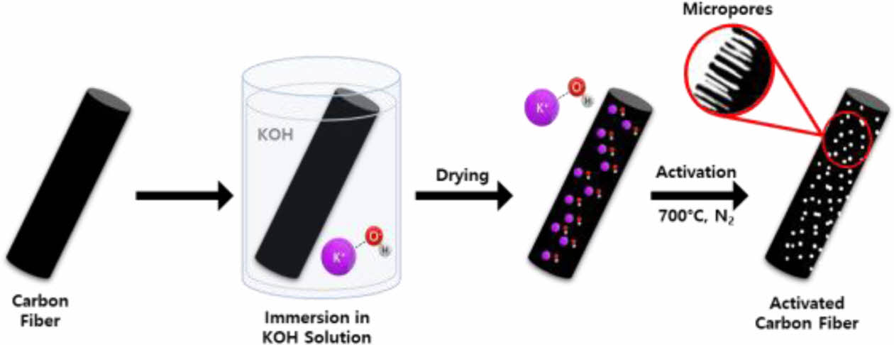
Scheme 1. Schematic depicting ACFs fabrication process from
PAN-based carbon fibers
2.2 Characterization
Scanning electron microscopy (SEM) images were obtained using EM-30 (COXEM, Korea). Thermal gravimetric analysis (TGA) was performed using TGA 550 system (TA instruments, USA) under an N₂ environment with a 10°C/min heating rate. To investigate the chemical structure of PAN and carbon materials, Raman spectroscopy (HEDA, WEVE, Korea) with 532 nm laser was used. The specific surface area was obtained based on the Brunauer-Emmett-Teller (BET) method using a TriStar II (Micromeritics Instrument Co., USA) at 77 K using liquid N₂. For CO₂ adsorption capacity, TriStar II (Micromeritics Instrument Co., USA) was also used with isothermal controller with temperature setting at 298 K.
3.1 Stabilization and Carbonization of PAN Precursor Fiber
Prior to fabrication of activated carbon materials with porous structure, carbonaceous materials should be prepared. PAN is the most widely utilized polymeric precursor in the production of carbonaceous materials. A two-step heat treatment including stabilization and carbonization is commonly employed to transform various polymeric precursors into carbonaceous materials [16,17]. The initial stage, known as the stabilization process, is conducted before the high-temperature carbonization process. Polymeric precursors are heat-treated in an atmospheric environment, typically within the temperature range of 200–400°C [18,19]. During this phase, the linear polymeric chains undergo thermal oxidation, leading to their conversion into thermally stable cyclic structures [20]. This transformation paves the way for the subsequent successful formation of a carbon structure during the high-temperature carbonization process. Following the stabilization process, carbonization takes place at elevated temperatures ranging from 800–1000°C under inert gas environments. This stage induces a rearrangement of the cyclized chains, culminating in the development of a well-defined carbon structure [20].
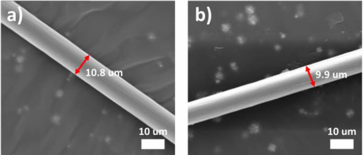
In this study, monofilament PAN fiber with diameter around 11 µm was prepared by wet spinning (Fig. 1-a). PAN fiber was then stabilized by thermal oxidation at 250°C. Upon thermal oxidation, the diameter of the fiber shrunk to 10 µm, which is a commonly observed phenomenon resulting from the formation of a cyclized chemical structure through thermal oxidation (Fig. 1-b).
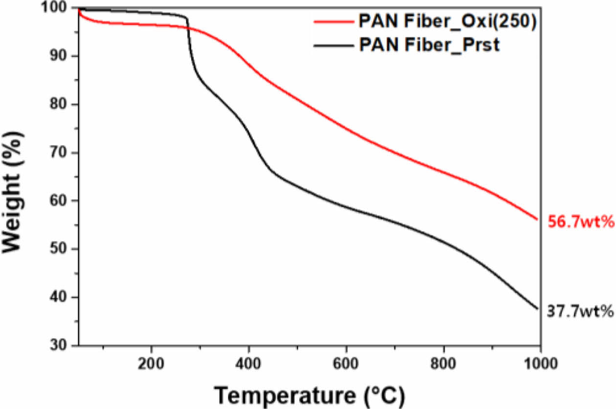
On top of the shrinkage in fiber diameter, TGA results proved successful stabilization via thermal oxidation (Fig. 2). Through TGA, samples went through high temperature heat treatment reaching 1000°C under N₂, which simulated carbonization process. While pristine PAN fiber, whose chemical structure did not contain thermally stable cyclic structure, exhibited final carbon yield of 37.7%, oxidized PAN fiber showed distinguishably improved carbon yield of 56.7%. Such improvement in carbon yield is mainly due to the formation of thermally stable cyclic structure by thermal oxidation.
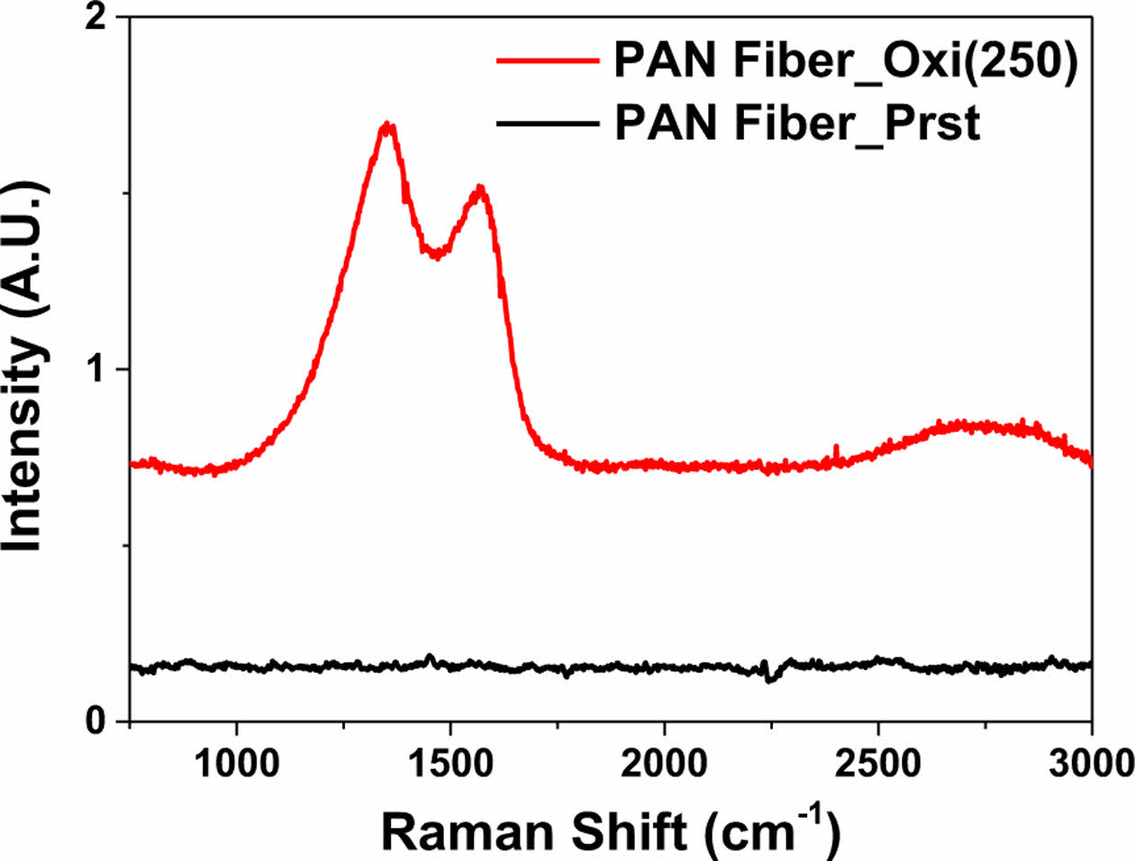
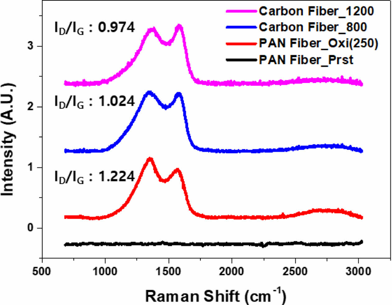
Finally, Raman spectroscopy again confirmed the successful stabilization of PAN fiber by oxidation at 250°C (Fig. 3). Emergence of D-band (1350 cm-1) and G-band (1582 cm-1) could be observed from the PAN fiber sample that underwent thermal oxidation, while the pristine counterpart did not show any traceable signal. As the D-band and G-band result from ring breathing vibrations and the in-plane stretching vibration of sp2 carbon atoms, respectively. Raman spectroscopy results could verify the formation of benzene rings, thus confirming the successful stabilization [21,22].
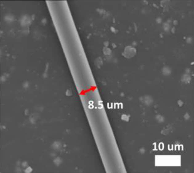
Next, thermal oxidatively stabilized PAN fiber went through carbonization. Carbonization was carried out at the 800°C, resulting in the successful fabrication of carbon fibers with an average diameter of 8.5 µm (Fig. 4).
Through Raman spectroscopy analysis, the ID/IG ratio can be obtained, which is the intensity ratio of the D-band and G-band. In typical PAN-based carbon fibers, this ratio is approximately 1, and it decreases as the crystallinity of the carbon structure increases [23]. ID/IG ratio of carbon fiber obtained from 800°C carbonization was 1.024, which indicated the successful fabrication of PAN-based carbon fibers (Fig. 5). Furthermore, with higher-temperature carbonization at 1200°C, the ID/IG ratio decreased from 1.024 to 0.974. This change corresponds to the pattern observed in PAN-based carbon materials [23,24].
3.2 Fabrication and the Characteristics of Activated Carbon Fibers
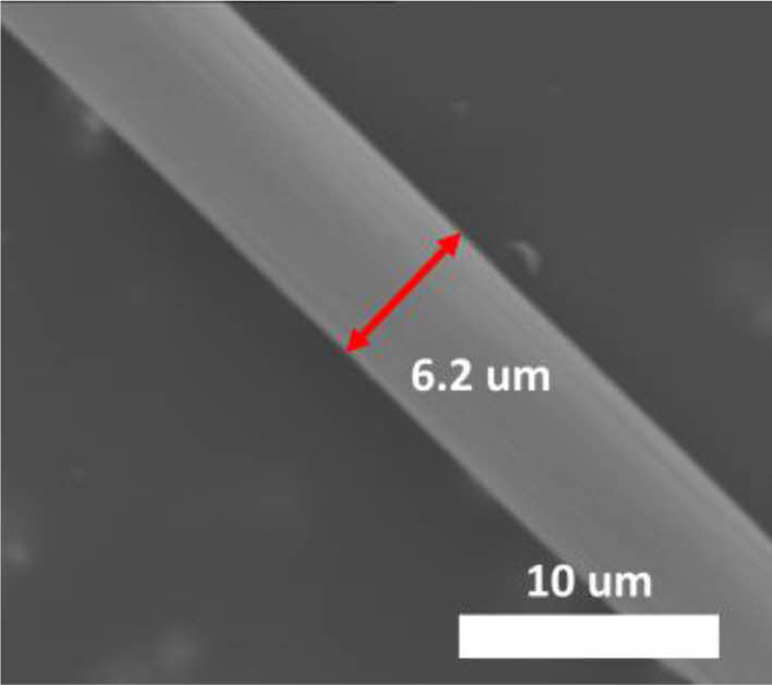
Next, ACFs were fabricated from PAN-based carbon fibers through chemical activation process using KOH. Various weight ratios, ranging from 1:1 to 1:4, of excess KOH were mixed with PAN-based carbon fibers and subsequently heat-treated at 700°C for activation. Samples were denoted as ACF-1 to ACF-4, corresponding to weight ratios ranging from 1:1 to 1:4. Morphological appearance of the all the ACFs did not vary a lot from the carbon fiber prior to activation. The SEM image of ACF-4, which is a representative image of all the ACFs, shows no significant morphological changes, except for a reduction in fiber diameter from 8.5 to 6.2 µm (Fig. 6).
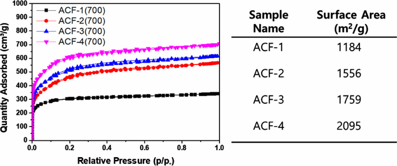
Still, the formation of a microporous structure, which is not easily discernible through SEM images, could be confirmed by analyzing the BET adsorption curves of ACFs (Fig. 7). The BET curves of all ACFs displayed the typical type-1 behavior associated with the formation of microporous structures [25,26]. The surface area of the ACFs significantly varied based on the KOH mixing ratio. From ACF-1 to ACF-4, surface area of the ACFs significantly increased from 1184 m2/g to 2095 m2/g.
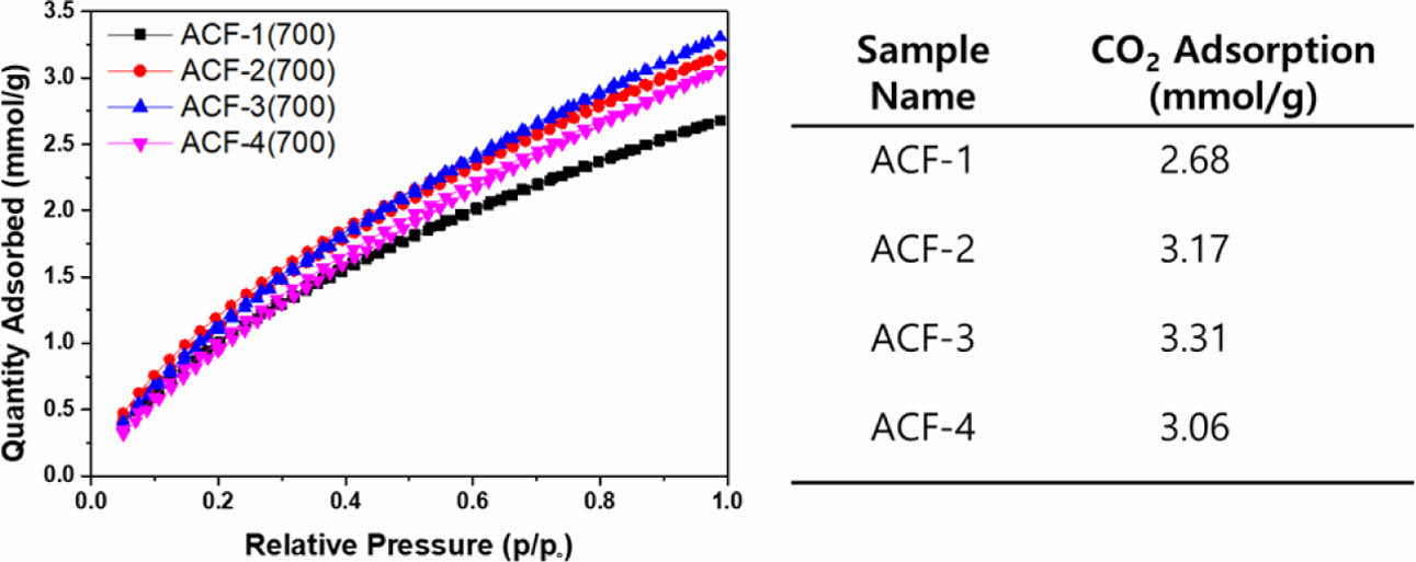
Next, CO₂ adsorption capacity of ACFs were determined by obtaining CO₂ adsorption isotherms using BET at 298K (Fig. 8). ACF-3 exhibited the highest CO₂ adsorption capacity reaching 3.31 mmol/g, which is comparable to previously reported values. ACFs fabricated based on electrospun PAN exhibited adsorption capacity of 2.68 and functionalized commercially available PAN based ACF fabrics exhibited adsorption capacity of 2.91 mmol/g, both of which are lower than that of ACF-3 [13,15]. However, the ACFs fabricated from pitch carbon fiber exhibited slightly higher adsorption capacity reaching 3.5 mmol/g [16].
However, the CO₂ adsorption capacity did not align with the trend in surface area. ACF-4, which exhibited the largest surface area of 2095 m2/g, could only adsorb 3.06 mmol/g of CO₂, a value similar as ACF-2, whose surface area was only 1556 m2/g.
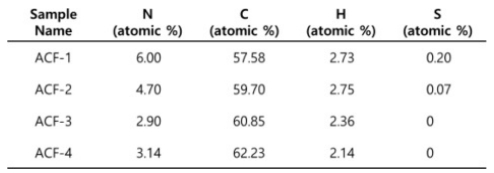
To scrutinize the disparity in CO₂ adsorption capacity, elemental analysis of samples was conducted because it is well known that nitrogen heteroatoms act as chemical adsorption sites for the CO₂ [27,28]. Elemental analysis revealed that ACF-2 contains a significantly greater amount of nitrogen heteroatoms than ACF-4 (Table 1).
It seems that this observation elucidates the comparable CO₂ adsorption capacity of ACF-2 despite having a significantly smaller surface area. However, nitrogen content cannot explain the higher CO₂ adsorption capacity of ACF-3 with lower nitrogen content than ACF-2. It is worthy to note that the instrumental accuracy of nitrogen content is approximately 0.3%. Therefore, the nitrogen content in ACF-3 can be regarded as similar to that of ACF-4. Then, if the nitrogen content is the determining factor for CO₂ adsorption capacity, ACF-2 should have a higher capacity, which is not observed here. In this case, it is highly expected that the ACF-3 has the largest volume of ultramicropore suitable for physical adsorption of CO₂. Ultramicropores smaller than 0.7 nm are known to govern the physical adsorption of CO₂ [25,26,29,30]. Simultaneously, higher KOH mixing ratio tends to etch out more amount of carbon. Despite ACF-4 having a higher surface area, the more extensively etched ACF-4 may possess micropores with a broader diameter distribution. This, in turn, may lead to an increased surface area associated with N₂ adsorption but a decreased CO₂ adsorption capacity.
|
Fig. 1 SEM images of a) pristine PAN fiber and b) stabilized PAN fiber |
|
Fig. 2 GA results of pristine and thermal oxidatively stabilized PAN fibers |
|
Fig. 3 Raman spectroscopy results of pristine and thermal oxidatively stabilized PAN fibers |
|
Fig. 4 SEM image of carbon fiber from stabilized PAN fiber |
|
Fig. 5 Raman spectroscopy results of stabilized PAN fiber and carbon fibers fabricated at varied temperatures |
|
Fig. 6 SEM image of activated carbon fiber from PAN-based carbon fiber |
|
Fig. 7 N2 adsorption curves of ACFs obtained at 77 K and the corresponding surface area calculated from the curves |
|
Fig. 8 CO2 adsorption curves of ACFs at 298 K and the corresponding adsorption capacity calculated from the curve |
|
Table 1 A table summarizing the atomic composition of ACFs tabulated by elemental analysis |
In this article, ACFs were derived from PAN precursor filaments. First, PAN-based carbon fibers were successfully fabricated via stabilization and carbonization processes, and resultant carbon fibers were chemically activated by varying weight ratios of KOH. ACFs, designated as ACF-1 to ACF-4 based on varying KOH mixing ratios from 1:1 to 1:4, displayed a consistent morphological appearance that did not differ from the morphology of carbon fibers before activation. Still, BET adsorption curves revealed the well-developed formation of microporous structures in all ACFs. The surface area varied with the KOH mixing ratio, increasing from 1184 m2/g to 2095 m2/g. But the CO₂ adsorption quantity did not correlate directly with the surface area. Elemental analysis highlighted that ACF-2 had a higher nitrogen content than ACF-4, which somewhat explains the comparable CO₂ adsorption capacity despite a smaller surface area. However, ACF-3 exhibited lower nitrogen content to ACF-2 but higher CO₂ adsorption capacity, which suggests that the factors beyond nitrogen content, such as micropore characteristics and distribution, play a more crucial role in CO₂ adsorption. Therefore, it was concluded that the ACF-3 has the optimal micropore volume and distribution suitable for physical adsorption of CO₂. In contrast, despite having a large surface area, ACF-4 is anticipated to experience excessive etching via KOH, resulting in a broader distribution of micropores that impede CO₂ adsorption.
This work was supported by the National Research Foundation of Korea (NRF) grant funded by the Korean Government (MSIT) (RS-2023-00221529 and 2020R1C1C1011817).
- 1. Heidarinejad, Z., Dehghani, M.H., Heidari, M., Javedan, G., Ali, I., and Sillanpää, M., “Methods for Preparation and Activation of Activated Carbon: A Review”, Environmental Chemistry Letters, Vol. 18, No. 2, 2020, pp. 393–415.
-

- 2. Danish, M., and Ahmad, T., “A Review on Utilization of Wood Biomass as a Sustainable Precursor for Activated Carbon Production and Application”, Renewable and Sustainable Energy Reviews, Vol. 87, 2018, pp. 1–21.
-
- 3. Yahya, M.A., Al-Qodah, Z., and Ngah, C.W.Z., “Agricultural Bio-Waste Materials as Potential Sustainable Precursors Used for Activated Carbon Production”, A Review.Renewable and Sustainable Energy Reviews, Vol. 46, 2015, pp. 218–235.
-
- 4. Rivera-Utrilla, J., Sánchez-Polo, M., Gómez-Serrano, V., Álvarez, P.M., Alvim-Ferraz, M.C.M., and Dias, J.M., “Activated Carbon Modifications to Enhance Its Water Treatment Applications.An Overview”, Journal of Hazardous Materials, Vol. 187, No. 1-3, 2011, pp. 1–23.
-
- 5. González-García, P., “Activated Carbon from Lignocellulosics Precursors: A Review of the Synthesis Methods, Characterization Techniques and Applications”, Renewable and Sustainable Energy Reviews, Vol. 82, 2018, pp. 1393–1414.
-
- 6. Wong, S., Ngadi, N., Inuwa, I.M., and Hassan, O., “Recent Advances in Applications of Activated Carbon from Biowaste for Wastewater Treatment: A Short Review”, Journal of Cleaner Production, Vol. 175, 2018, 175, pp. 361–375.
-
- 7. Chai, W.S., Cheun, J.Y., Kumar, P.S., Mubashir, M., Majeed, Z., Banat, F., Ho, S.H., and Show, P.L., “A Review on Conventional and Novel Materials Towards Heavy Metal Adsorption in Wastewater Treatment Application”, Journal of Cleaner Production, Vol. 296, 2021, pp. 126589.
-
- 8. Zhang, X., Gao, B., Creamer, A.E., Cao, C., and Li, Y., “Adsorption of VOCs onto Engineered Carbon Materials: A Review”, Journal of Hazardous Materials, Vol. 338, 2017, pp. 102–123.
-
- 9. Gironi, F., and Piemonte, V., “VOCs Removal from Dilute Vapour Streams by Adsorption onto Activated Carbon”, Chemical Engineering Journal, Vol. 172, No. 2-3, 2011, pp. 671–677.
-
- 10. Yusof, N., and Ismail, A.F., “Post Spinning and Pyrolysis Processes of Polyacrylonitrile (PAN)-Based Carbon Fiber and Activated Carbon Fiber: A Review”, Journal of Analytical and Applied Pyrolysis, Vol. 93, 2012, pp. 1–13.
-
- 11. Sidheswaran, M.A., Destaillats, H., Sullivan, D.P., Cohn, S., and Fisk, W.J., “Energy Efficient Indoor VOC Air Cleaning with Activated Carbon Fiber (ACF) Filters”, Building and Environment, Vol. 47, No. 1, 2012, pp. 357–367.
-
- 12. Zhang, L., Tu, L.Y., Liang, Y., Chen, Q., Li, Z.S., Li, C.H., Wang, Z.H., and Li, W., “Coconut-Based Activated Carbon Fibers for Efficient Adsorption of Various Organic Dyes”, RSC Advances, Vol. 8, No. 74, 2018, pp. 42280–42291.
-
- 13. Wang, J., Park, Y.K., and Jo, Y.M., “Sequential Improvement of Activated Carbon Fiber Properties for Enhanced Removal Efficiency of Indoor CO₂”, Journal of Industrial and Engineering Chemistry, Vol. 89, No. 25, 2020, pp. 400–408.
-
- 14. Kim, D.W., Jung, D.W., Adelodun, A.A., and Jo, Y.M., “Evaluation of CO₂ Adsorption Capacity of Electrospun Carbon Fibers with Thermal and Chemical Activation”, Journal of Applied Polymer Science, Vol. 134, No. 47, 2017, pp. 1–8.
-
- 15. Chiang, Y.C., Yeh, C.Y., and Weng, C.H., “Carbon Dioxide Adsorption on Porous and Functionalized Activated Carbon Fibers”, Applied Sciences, Vol. 9, No. 10, 2019, pp. 1977.
-
- 16. Diez, N., Alvarez, P., Granda, M., Blanco, C., Santamaria, R., and Menendez, R., “CO₂ Adsorption Capacity and Kinetics in Nitrogen-enriched Activated Carbon Fibers Prepared by Different Methods”, Chemical Engineering Journal, Vol. 281, No. 1, 2015, pp. 704–712.
-
- 17. Lee, J., Kim, J., Hyeon, T., “Recent Progress in the Synthesis of Porous Carbon Materials”, Advanced Materials, Vol. 18, No. 16, 2006, pp. 2073–2094.
-
- 18. Nataraj, S.K., Yang, K.S., and Aminabhavi, T.M., “Polyacrylonitrile-Based Nanofibers - A State-of-the-Art Review”, Progress in Polymer Science, Vol. 37, No. 3, 2012, pp. 487–513.
-
- 19. Khayyam, H., Jazar, R.N., Nunna, S., Golkarnarenji, G., Badii, K., Fakhrhoseini, S.M., Kumar, S., and Naebe, M., “PAN Precursor Fabrication, Applications and Thermal Stabilization Process in Carbon Fiber Production: Experimental and Mathematical Modelling”, Progress in Materials Science, Vol. 107, 2020, pp. 100575.
-
- 20. Frank, E., Steudle, L.M., Ingildeev, D., Spörl, J.M., and Buchmeiser, M.R., “Carbon Fibers: Precursor Systems, Processing, Structure, and Properties”, Angewandte Chemie International Edition, Vol. 53, No. 21, 2014, pp. 5262–5298.
-
- 21. Ferrari, A.C., and Robertson, J., “Interpretation of Raman Spectra of Disordered and Amorphous Carbon”, Physical Review B, Vol. 61, No. 20, 2000, pp. 14095–14107.
-
- 22. Ferrari, A.C., and Basko, D.M., “Raman Spectroscopy as a Versatile Tool for Studying the Properties of Graphene”, Nature Nanotechnology, Vol. 8, No. 4, 2013, pp. 235–246.
-
- 23. Lee, S., Kim, J., Ku, B.-C., Kim, J., and Joh, H.-I., “Structural Evolution of Polyacrylonitrile Fibers in Stabilization and Carbonization”, Advances in Chemical Engineering and Science, Vol. 2, No. 2, 2012, pp. 275–282.
-
- 24. Son, S.-Y., Noh, Y.-J., Bok, C., Lee, S., Kim, B.G., Na, S.-I., and Joh, H.-I., “One-Step Synthesis of Carbon Nanosheets Converted from a Polycyclic Compound and Their Direct Use as Transparent Electrodes of ITO-Free Organic Solar Cells”, Nanoscale, Vol. 6, No. 2, 2014, pp. 678–682.
-
- 25. Casco, M.E., Martínez-Escandell, M., Silvestre-Albero, J., and Rodríguez-Reinoso, F., “Effect of the Porous Structure in Carbon Materials for CO₂ Capture at Atmospheric and High-Pressure”, Carbon, Vol. 67, 2014, pp. 230–235.
-
- 26. Yurduşen, A., Yürüm, A., and Yürüm, Y., “The Role of Ultramicropores in the CO₂ Adsorption Capacity of Fe-BTC Crystallites Synthesized with a Perturbation-Assisted Nanofusion Synthesis Strategy”, CrystEngComm, Vol. 22, No. 5, 2020, pp. 932–944.
-
- 27. Sethia, G., and Sayari, A., “Comprehensive Study of Ultra-Microporous Nitrogen-Doped Activated Carbon for CO₂ Capture”, Carbon, Vol. 93, 2015, pp. 68–80.
-
- 28. Li, D., Chen, Y., Zheng, M., Zhao, H., Zhao, Y., and Sun, Z., “Hierarchically Structured Porous Nitrogen-Doped Carbon for Highly Selective CO₂ Capture”, ACS Sustainable Chemistry & Engineering, Vol. 4, No. 1, 2016, pp. 298–304.
-
- 29. Hu, B., Cheng, Y., Wang, Z., He, X., Jiang, Z., Yi, M., Li, W., and Wang, L., “Effect of Pulverization on the Microporous and Ultramicroporous Structures of Coal Using Low-Pressure CO₂ Adsorption”, Energy and Fuels, Vol. 33, No. 11, 2019, pp. 10611–10621.
-
- 30. Liu, Z., Zhang, Z., Jia, Z., Zhao, L., Zhang, T., Xing, W., Komarneni, S., Subhan, F., and Yan, Z., “New Strategy to Prepare Ultramicroporous Carbon by Ionic Activation for Superior CO₂ Capture”, Chemical Engineering Journal, Vol. 337, 2018, pp. 290–299.
-
 This Article
-
2023; 36(6): 402-407
Published on Dec 31, 2023
- 10.7234/composres.2023.36.6.402
- Received on Nov 21, 2023
- Revised on Nov 27, 2023
- Accepted on Dec 22, 2023
Services
- Abstract
1. introduction
2. materials and methods
3. result and discussions
4. conclusions
- Acknowledgements
- References
- Full Text PDF
Shared
Correspondence to
- Inchan Yang*, Doo-Won Kim**, Dalsu Choi***
-
* Carbon Materials Research Group, Research Institute of Industrial Science & Technology (RIST), Pohang 37673, Republic of Korea Convergence R&D Division, Korea
** Carbon Industry Promotion Agency (KCARBON), Jeonju-si, Jeollabuk-do 54852, Republic of Korea
*** Chemical Engineering Department, Myongji University, 116, Myongji-ro, Cheoin-gu, Yongin-si, Gyeonggi-do 17058, Republic of Korea - E-mail: dalsuchoi@mju.ac.kr, iyang@rist.re.kr, doowon@kcar
Gangnam Mirae Tower, Suite 601, 174 Saimdang-ro, Seocho-gu, Seoul 06627, South Korea
Tel: +82-2-598-1550 Fax: +82-2-598-1557 E-mail: composites@kscm.re.kr