


- A Method to Classify Recycled Carbon Fibers by Length in Rotating Viscous Fluid
Hyeong Woo Kang*, Junseong Byeon*, Seongyun Ahn*, Yeongmin Park*, Jae-hyeon Ha**, Sang Yup Kim*†
*Department of Mechanical Engineering, Sogang University, Seoul, Republic of Korea
**Catech-H Technical Research Center, Jeollabuk-do, Republic of KoreaThis article is an open access article distributed under the terms of the Creative Commons Attribution Non-Commercial License (http://creativecommons.org/licenses/by-nc/4.0) which permits unrestricted non-commercial use, distribution, and reproduction in any medium, provided the original work is properly cited.
As products made of carbon fiber reinforced polymers (CFRP) reach the end of their operational lifespan, conventional recycling techniques, such as pyrolysis, have demonstrated limitations by producing short and damaged recycled carbon fiber. Recently, chemical recycling techniques have become increasingly prominent due to their capacity to separate reinforcing fibers with minimal degradation. To fully leverage the benefits of chemical recycling for efficient production, it is essential to sort the length of recycled carbon fibers and produce quality recycled carbon fiber polymer composites (r-CFRP) with high efficiency. In this study, we propose a method for lengthwise classification of carbon fibers using the distinction movement of fibers exhibited in a rotational flow of a viscous medium. In order to elucidate the underlying mechanism, a simplified one-dimensional Couette flow model is implemented. Moreover, experiments are conducted to validate the classification efficiency of the proposed method.
Keywords: CFRP Recycling, Fiber classification, Recycled carbon fiber
Carbon fiber reinforced polymers (CFRP) have been widely utilized due to their lightweight and high strength and stiffness. The global demand for carbon fiber is expected to reach 117 kilotons, and 194 kilotons for CFRP in 2022 [1,2]. For instance, the Airbus A350 and Boeing 787 Dreamliner, the latest wide-body aircraft, have increased their use of CFRP, which now accounts for more than 50% of their weight [3]. As the use of CFRP increases, the amount of CFRP to be recycled in the future also increases notably. The global CFRP waste is projected to increase to 20 kt annually by 2025 [1], with approximately 6000-8000 commercial aircraft reaching their end-of-life by 2030 [4]. Therefore, the need for recycling technology is growing.
Carbon fiber recycling involves separating carbon fiber reinforcement from the composite structure [5]. Separated carbon fiber is primarily used in the production of recycled carbon fiber reinforced polymer (r-CFRP), which finds applications in various industries such as automobile [6], wind turbine blades [7,8], and carbon fiber-reinforced concrete [9,10]. For instance, BMW uses non-woven recycled carbon fiber composite for the seats and roof of its i3 and i8 models. Recycled carbon fiber can decrease costs by 70% and energy costs by almost 98% which presents an enormous prospect for production cost reduction [11]. Another application of recycled carbon fiber is in reinforced self-compacting concrete, the incorporation of recycled carbon fiber into concrete has demonstrated noteworthy enhancements in stiffness and strength [12].
The mechanical properties of r-CFRP are heavily influenced by fiber length and orientation.In recycled carbon fiber composites, increasing the volume fraction and length of fibers enhances the reinforcing effect and improves the composite’s mechanical properties [13]. Furthermore, long carbon fibers aid in their alignment, resulting in a significant increase in normalized tensile strength and modulus [14]. Also in recycled carbon fiber-reinforced concrete, increasing fiber volume fraction and length improves composite's mechanical properties and impact resistance [12].
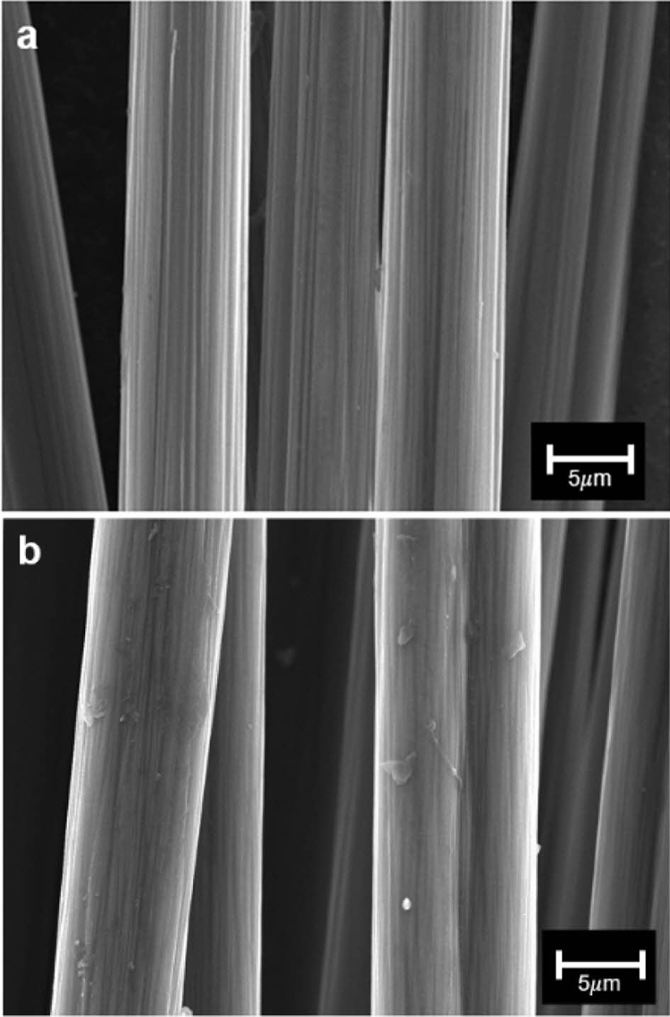
Current methods for carbon fiber recycling include grinding, pyrolysis, and chemical processes. To date, only pyrolysis and grinding are viable at an industrial scale [15]. However, ground fiber retains significant matrix residue, negatively affecting composite quality, and the short length of the fiber limits its use [16]. Pyrolysis is an energy-intensive process that also has the potential to negatively impact the environment, and it results in the degradation of fiber quality and length [17,18]. As a result, chemical methods are gaining attention due to their environmental friendly conditions and low-destruction processing. Chemically processed recycled carbon fiber typically yields greater than 90% strength retention [19]. As shown in Fig. 1, the surface of chemically recycled carbon fiber appears largely undamaged compared to neat carbon fiber, indicating the gentle nature of the chemical recycling process. This preservation of surface integrity is crucial for maintaining the mechanical properties of the recycled fiber reinforced composite.
During the chemical recycling process, continuous carbon fibers separate into discrete fibers of random length due to their brittle nature [20]. Therefore, lengthwise classification of recycled carbon fibers is essential to enhance the property of r-CFRP. Most current classification technologies mainly focus on the particles with small aspect ratios. Fiber sorting technology has primarily been restricted to small-batch quality control in the paper and food industries, with limited academic attention. After the 1980s, Baron developed the Baron classifier, using electrophoresis to classify micro-sized fibers, such as aerosols, by length [21]. However, the Baron fiber classifier is limited to classifying short fibers up to 30 micrometers. Moreover, classification based on aerodynamic characteristics has limitations due to the potential health risks from inhaling nano-sized materials [22,23]. As the importance of sustainable fiber composite production is growing, it is essential to develop a non-destructive carbon fiber length sorting mechanism at the macro scale.
Herein, we present the lengthwise classification mechanism of recycled carbon fibers based on differences in fiber movement in a shear stress field of a rotating fluid. We demonstrate the classification by adjusting rotational shear flows of a sodium alginate solution, which is an environmental friendly thixotropic medium capable of stabilizing Couette flow by high viscosity.
|
Fig. 1 Scanning electron microscopy (SEM) images of (a) neat carbon fiber and (b) chemically recycled carbon fiber. The recycled carbon fiber demonstrates that the surface is not significantly damaged during the chemical recycling process |
2.1 Materials
Sodium alginate powder is purchased from Qingdao Bright Moon Seaweed Group Co., Ltd (China) and is mixed with water to prepare sodium alginate hydrogel medium. An overhead stirrer mixer (COS-100) from CAS Co., Ltd., (Rep. of Korea) stirs 0.7 wt.% Sodium alginate-water medium at 500 rpm for 1 hour. The solution is stirred before each use to ensure homogeneity. The carbon fiber tow strands are derived from 3k carbon twill weave from FRP SHOP (Rep. of Korea) and do not have any visible split ends. Chemically recycled carbon fiber is supplied by CATECH-H (Rep. of Korea). Classification rods are fabricated using a 3D printer (CUBICON) and surface-treated with 2000-grit sandpaper.
2.2 Experimental setup
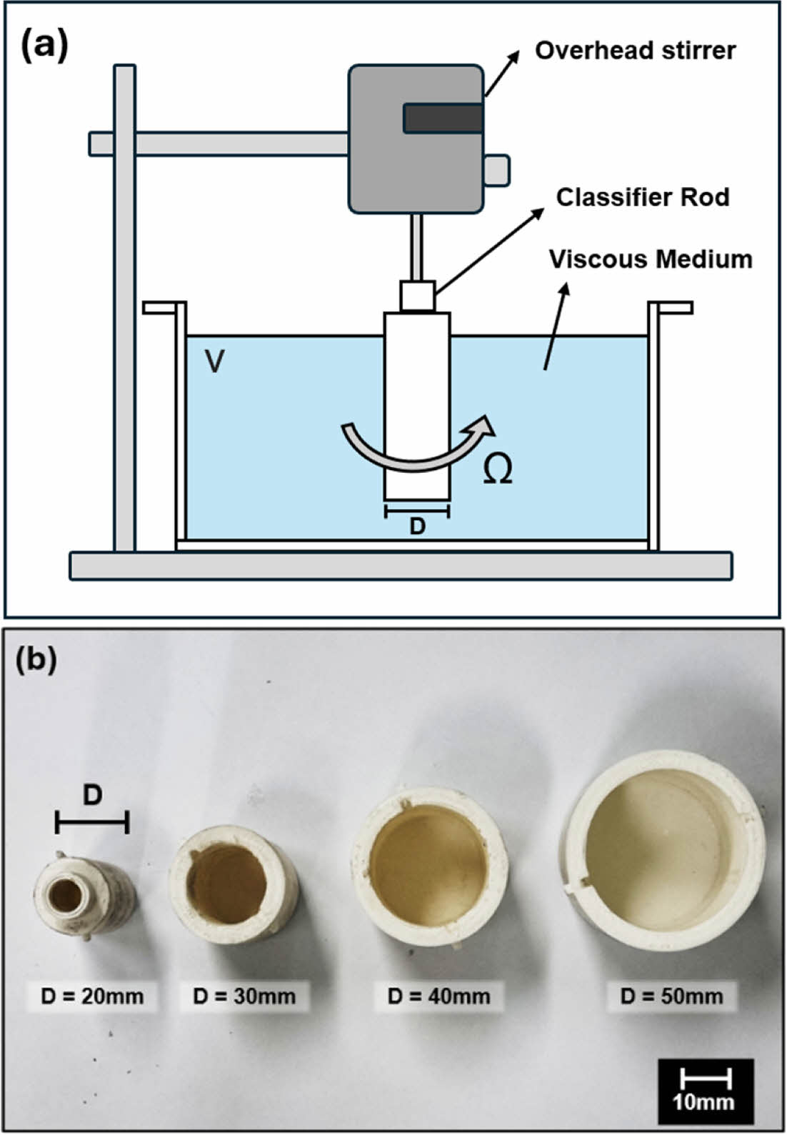
As shown in Fig. 2, The classification setup includes a stirrer module that generates constant rotational shear flow and a cylindrical water bath where the classification occurs. The classification rods with diameters of 20 mm, 30 mm, and 40 mm, are placed at the center of the bath and elevated 2 cm above the floor to reduce asymmetric turbulence. After the fluid reaches a steady state, a carbon fiber tow is positioned 20 cm from the rotation center and 1cm below the level. The time taken for 90% of the entire fibers to be captured by the classification rod is measured. Fiber movement during the capturing process is recorded with a DSLR camera and analyzed using Tracker software (Open-Source Physics). The capture time for fibers of varying lengths (10, 30, 50, and 70 mm) is measured. Fibers that continue to rotate without capture for more than three minutes are classified as uncaptured.
2.3 Characterization methods
In order to verify the Couette flow characteristics of viscous fluids, ink droplets are introduced into flow generated by a 20mm rod rotating at 250 rpm. Their azimuthal velocities are measured using the Tracker software and compared with results from the 1D Couette model.
|
Fig. 2 (a) Schematic of experimental setup. An overhead stirrer rotates a rod immerged in a viscous medium to generate shear flow. (b) Photo images of 3D-printed rods used to generate shear flow and capture fibers |
3.1 Behavior of fibers in rotational shear fluid
A Taylor-Couette flow is a steady flow created between two rotating infinitely long coaxial cylinders. Since the cylinder lengths are infinitely long, the flow is essentially unidirectional in a steady state. If the inner cylinder with radius Ri is rotating at constant angular velocity Ωi and the outer cylinder with radius Ro is rotating at constant angular velocity Ωo, then the azimuthal velocity component Vq at the radial distance r from the center of the inner cylinder is given by [24]:
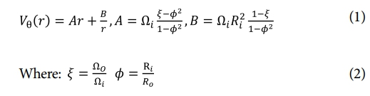
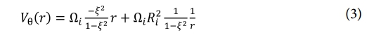
In a stationary circular bath with no angular velocity, the velocity expression can be represented as:
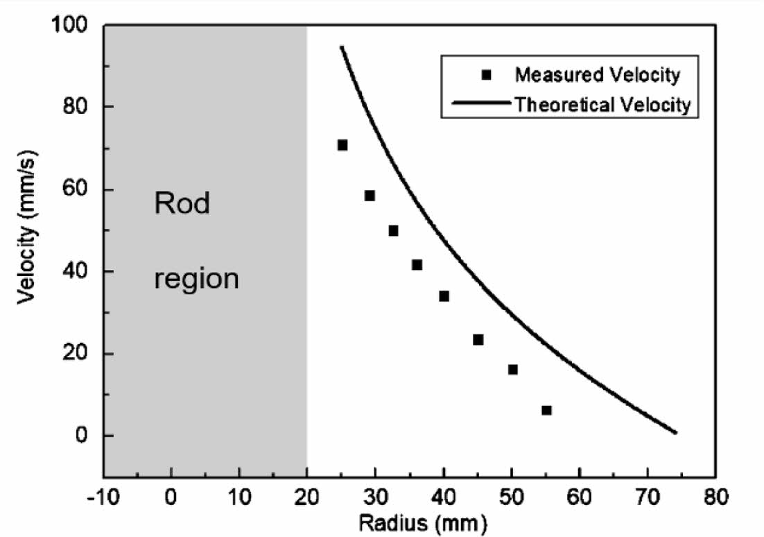
As indicated by this expression, the fluid velocity in Couette flow decreases as the distance from the center increases. This trend aligns with the velocity measurement outcomes shown in Fig. 3. In comparison to the theoretical velocity, the observed velocity is typically lower. We hypothesize this discrepancy is attributed to the viscosity of the fluid.
The establishment of a stable flow field is essential for ensuring the consistency of fiber classification. However, when the angular velocity of the inner cylinder exceeds a certain threshold, Couette flow becomes unstable, transitioning to a secondary steady state with axisymmetric toroidal vortices. The Taylor number is often used to confirm the stability of the flow and defined as:
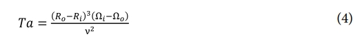
Where n is the kinematic viscosity. When the Taylor number exceeds the critical threshold, periodic disturbances called Taylor vortices emerge. Increasing viscosity reduces the Taylor number, potentially preventing Taylor vortices and resulting in a stabilized flow. Since our experiments used a high-viscosity sodium alginate medium, the flow can be approximated as 1D Couette flow.
3.2 Classification mechanism
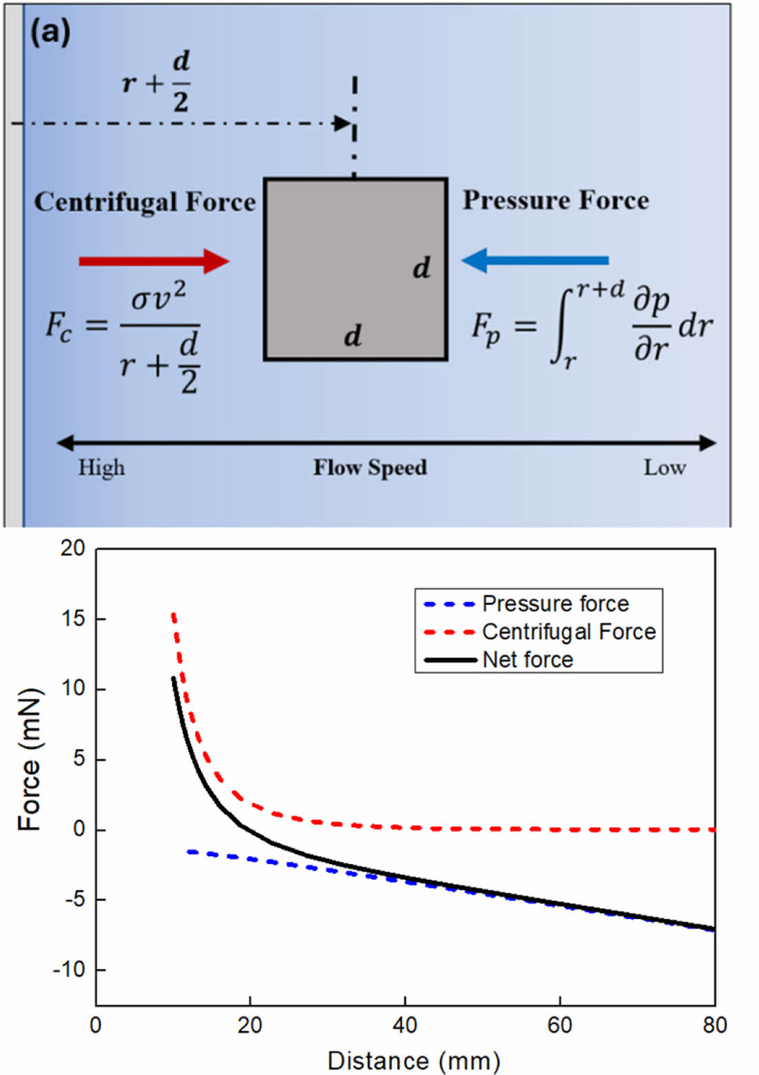
In Couette flow, shear flow develops with a velocity gradient that decreases as the distance from the center increases, due to shear stress. This velocity gradient generates a pressure gradient, as per Bernoulli’s law, which directs fibers toward the cylinder's center. Additionally, the velocity of moving fibers generates a centrifugal force that pushes fiber outward. Fig. 4(a) provides an illustration of the forces acting on a fiber in this environment, while Fig. 4(b) demonstrates how the net force direction changes based on the diameter-to-distance ratio.
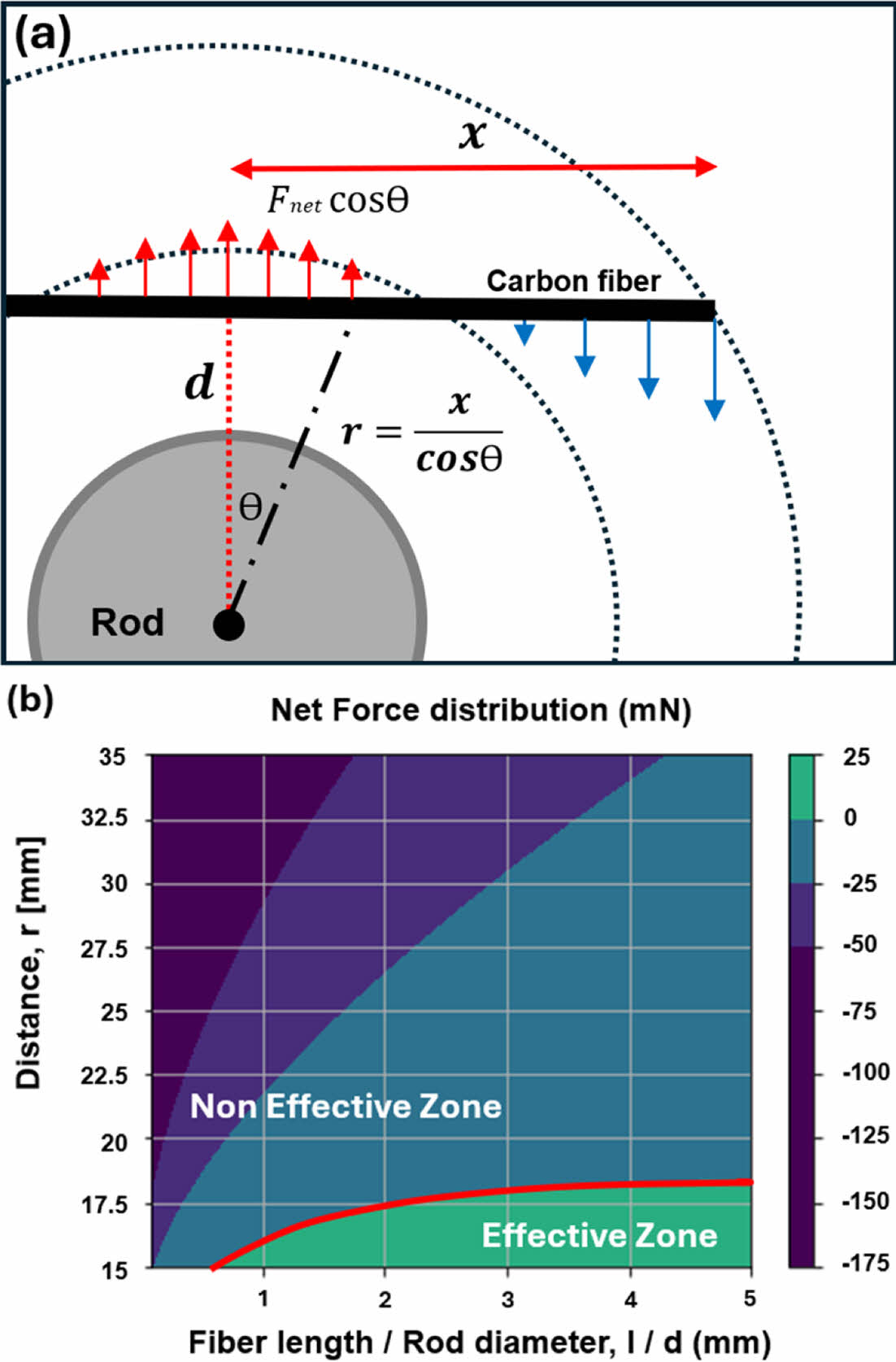
Assuming the fibers are rigid straight bodies, a simplified model, as illustrated in Fig. 5(a), reveals fiber behavior based on their length within a rotating cylinder. The fundamental mechanism is the interplay between a pressure gradient, driving longer fibers inward, and centrifugal forces, pushing shorter fibers outward. Fig. 5(b) visually confirms these opposing forces, showing that for fibers with a length-to-diameter ratio less than 1, the net force is consistently directed outward. This difference in net force leads to the classification of fibers based on their length, directing relatively longer fibers towards the center, where the pressure decreases towards the axis of rotation, and causing shorter fibers to follow the rotational flow and stay near the periphery.
The observed trends in simulations are preliminary and provide only a general indication of the behavior. To achieve more precise results, further research is necessary to refine the simulation parameters and account for additional factors affecting the critical length. These results confirm that fiber length significantly affects classification behavior in rotational flow, and the proposed mechanism shows potential for effective fiber length classification in recycling processes.
|
Fig. 3 Theoretical and measured velocity as a function of distance from the center in a one-dimensional Couette flow. Overall, the measured values are found to be lower than the theoretical values, which is likely due to the viscosity of the fluid |
|
Fig. 4 (a) Illustration of force acting on fiber with a squareshaped cross-section immersed in a fluid. (b) Force acting on an object in a shear flow stress field by a 20mm diameter rod. The net force direction acting on the fiber changes at a diameter-to-distance ratio of approximately 1 |
|
Fig. 5 (a) Schematic illustration of the net force acting on a fiber in a rotational shear flow field. (b) Net force simulation results in a rotational flow field made by a cylindrical rod with a diameter of 20mm. In a fiber with a short length (length/diameter < 1), the force always acts in an outer direction at every position. As the fiber length increases, when the fiber is in proximity to the classification rod, the force acts in an inner direction toward the cylinder, thereby capturing the fiber to the classification cylinder |
In order to evaluate the feasibility of sorting recycled carbon fiber, we conducted an experiment to measure the capture time for the fiber based on the length of the carbon fiber and the diameter of the rod that generates the flow. It is anticipated that this discrepancy in behavior can serve as a mechanism for fiber classification, enabling sorting based on whether fibers are captured.
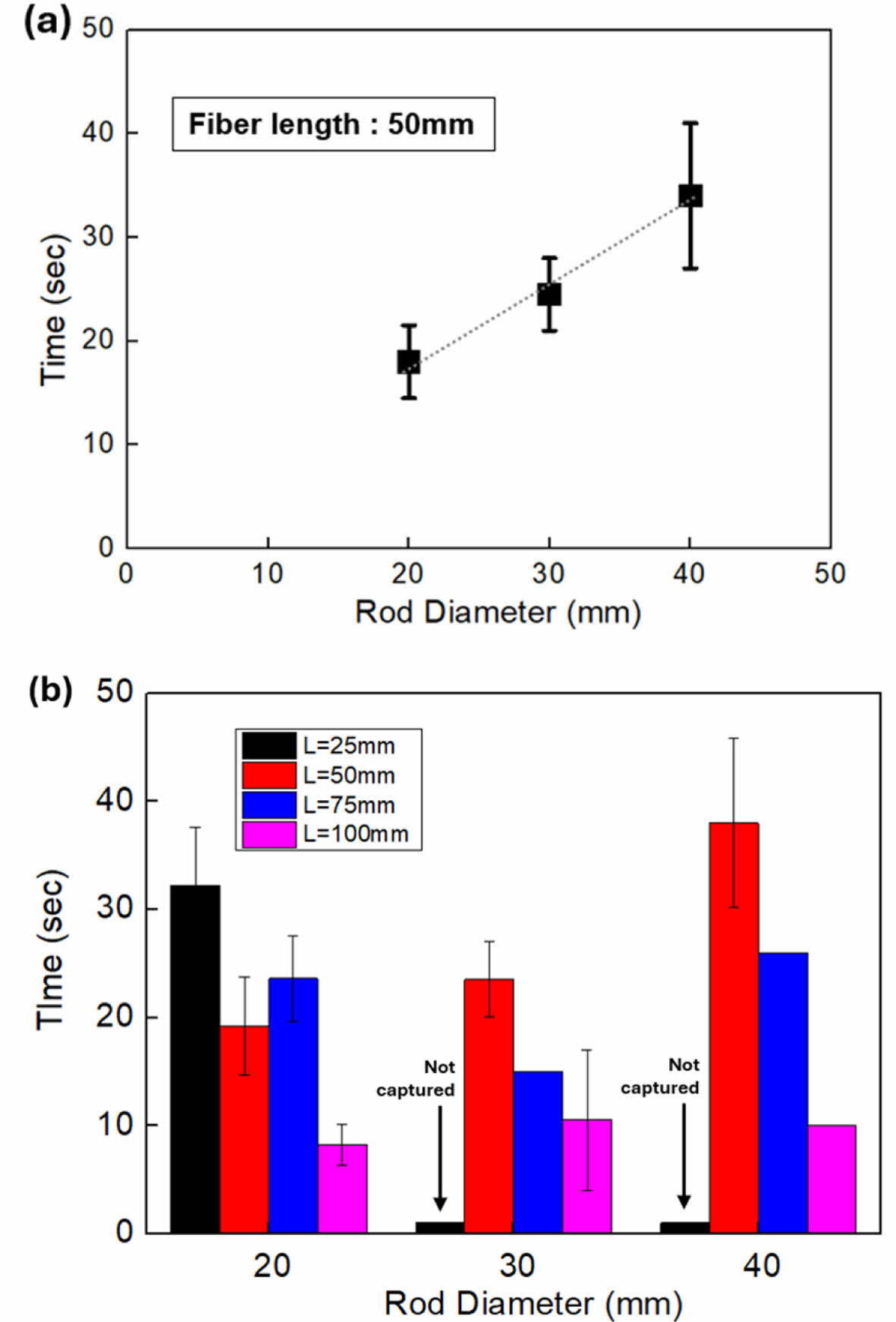
Fig. 6(a) illustrates the influence of rod diameter on capture time, under the same fiber length condition. It can be observed that as the rod diameter increases, the required capture time also increases. This is attributed to the rotational flow velocity increasing with rod diameter, causing a greater centrifugal force on the fiber. Concurrently, an increase in rod diameter is accompanied by a linear rise in capture time. Since the diameter and velocity of the fluid are proportional at a constant angular velocity, it can be inferred that the relationship between fluid velocity and capture time is also proportional.
Fig. 6(b) illustrates the capture time for rod diameters of 20 mm, 30 mm, and 40 mm and fiber lengths of 25 mm, 50 mm, 75 mm, and 100 mm. It can be observed that the capture time decreases as the fiber length increases for all rod diameters with the exception of 20 mm. This is consistent with the simulation results of the model described earlier, which demonstrated that the influence of pressure force increases as the length of the fiber increases. The differing trend observed at the 20mm diameter is likely due to flow slippage caused by the viscosity of the medium, thereby preventing the formation of a gradient.
During the experiment, fibers of shorter than diameter length are not captured as they approach the rod; rather, they are ejected while undergoing rotation with the rod. Fibers that are not captured by the rod for a period exceeding three minutes are deemed to be incapable of being captured. The probability of capture decreases with increasing the length of the fiber and the diameter of the rod. In cases where the fiber length is shorter than the rod diameter, the fiber is observed to exhibit non-capture behavior in all instances. It is anticipated that the classification of fibers according to their capture status can be achieved even in a scaled-up setup.
While we propose a lengthwise fiber sorting mechanism, its practical utility remains limited by the unresolved issue of fiber entanglement. To assess the viability of implementing this mechanism in an industry, the mass sorting process is conducted using recycled carbon fiber. However, due to fiber entanglement and inter-fiber interactions, multiple fibers are introduced simultaneously, which constitutes a significant limitation. Further research is required to minimize entanglement to enhance the usability of the sorting mechanism.
|
Fig. 6 (a) Fiber capturing time for rod diameter d=20, 30, 40mm. Longer capture times with increasing diameter showcase the potential for fiber classification based on behavior differences. (b) Graph of fiber capturing time as a function of fiber length and rod diameter. Any fibers not captured for a period exceeding two minutes were assumed to be uncaptured. Capture time decreased as fiber length increased across all rod diameters. The error bars in the graph represent the standard deviation calculated from three independent experiments |
We propose a new lengthwise fiber classification mechanism using the behavioral difference in the rotating shear flow of viscous fluid. Sodium alginate, an eco-friendly and non-toxic viscous medium, is used to generate a stable shear stress field with reduced Taylor vortices, and the behavior of fibers moving in the stress field is analyzed using a 1D Couette model. Small batch classification experiments are conducted to test the applicability of the method, and it is found that the capturing time varies depending on the length of the fiber and the diameter of the capturing rod. this method enables non-destructive fiber processing while fibers remain impregnated, eliminating the need for the energy-consuming drying process after the chemical recycling process.
A mass-scale classification of recycled carbon fiber is conducted to investigate the feasibility of industrialization. However, the classification process proves unfeasible due to the intrinsic entanglement characteristics of carbon fibers. Developing effective methods to manage entanglement will be a crucial aspect to address for future scale-up efforts.
By results in an improvement in the performance of recycled carbon fiber composites and a broadening of their range of applications, This approach is expected to contribute to more sustainable composite use.
This work was supported by the Sogang University LINC 3.0 (Grant number: 202380002.02), CATACH-H Co., Ltd and Hyundai Motor Chung Mong-Koo Foundation.
- 1. J. Zhang, V. S. Chevalier, H. Wang, and C.-H. Wang, “Current Status of Carbon Fibre and Carbon Fibre Composites Recycling,” Composites Part B: Engineering, Vol. 193, 2020, p. 108053, doi: 10.1016/j.compositesb.2020.108053.
-

- 2. S. Hegde, B. Satish Shenoy, and K. N. Chethan, “Review on Carbon Fiber Reinforced Polymer (CFRP) and Their Mechanical Performance,” Materials Today: Proceedings, Vol. 19, 2019, pp. 658-662, doi: 10.1016/j.matpr.2019.07.749.
-
- 3. N. Feng, X. Wang, and D. Wu, “Surface Modification of Recycled Carbon Fiber and its Reinforcement Effect on Nylon 6 Composites: Mechanical Properties, Morphology and Crystallization Behaviors,” Current Applied Physics, Vol. 13, No. 9, 2013, pp. 2038-2050, doi: 10.1016/j.cap.2013.09.009.
-
- 4. V. P. McConnell, “Lausnching the Carbon Fibre Recycling Industry,” Reinforced Plastics, Vol. 54, No. 2, 2010, pp. 33-37, doi: https://doi.org/10.1016/S0034-3617(10)70063-1.
-
- 5. D. Borjan, Ž. Knez, and M. Knez, “Recycling of Carbon Fiber-Reinforced Composites—Difficulties and Future Perspectives,” Materials, Vol. 14, No. 15, 2021, p. 4191, doi: 10.3390/ma14154191.
-
- 6. A. B. Balaji, C. Rudd, and X. Liu, “Recycled Carbon Fibers (rCF) in Automobiles: Towards Circular Economy,” Mater Circ Econ, Vol. 2, No. 1, 2020, p. 4, doi: 10.1007/s42824-020-00004-0.
-
- 7. V. K. K. Upadhyayula et al., “Wind Turbine Blades Using Recycled Carbon Fibers: An Environmental Assessment,” Environmental Science & Technology Journal, Vol. 56, No. 2, 2022, pp. 1267-1277, doi: 10.1021/acs.est.1c05462.
-
- 8. J. Chen, J. Wang, and A. Ni, “Recycling and reuse of composite materials for wind turbine blades: An overview,” Journal of Reinforced Plastics and Composites, Vol. 38, No. 12, 2019, pp. 567-577, doi: 10.1177/0731684419833470.
-
- 9. M. Bhandari and I.-W. Nam, “A Critical Review on the Application of Recycled Carbon Fiber to Concrete and Cement Composites,” Recycling, Vol. 9, No. 1, 2024, p. 17, doi: 10.3390/recycling9010017.
-
- 10. A. Danish et al., “Utilization of Recycled Carbon Fiber Reinforced Polymer in Cementitious Composites: A Critical Review,” Journal of Building Engineering, Vol. 53, 2022, p. 104583, doi: 10.1016/j.jobe.2022.104583.
-
- 11. E. Shehab, A. Meiirbekov, A. Amantayeva, A. Suleimen, S. Tokbolat, and S. Sarfraz, “A Cost Modelling System for Recycling Carbon Fiber-Reinforced Composites,” Polymers, Vol. 13, No. 23, 2021, p. 4208, doi: 10.3390/polym13234208.
-
- 12. M. Mastali, A. Dalvand, and A. Sattarifard, “The Impact Resistance and Mechanical Properties of the Reinforced Self-compacting Concrete Incorporating Recycled CFRP Fiber with Different Lengths and Dosages,” Composites Part B: Engineering, Vol. 112, 2017, pp. 74-92, doi: 10.1016/j.compositesb.2016.12.029.
-
- 13. A. Fernández, M. Santangelo-Muro, J. P. Fernández-Blázquez, C. S. Lopes, and J. M. Molina-Aldareguia, “Processing and Properties of Long Recycled-carbon-fibre Reinforced Polypropylene,” Composites Part B: Engineering, Vol. 211, 2021, p. 108653, doi: 10.1016/j.compositesb.2021.108653.
-
- 14. J. Ivars, A. R. Labanieh, and D. Soulat, “Effect of the Fibre Orientation Distribution on the Mechanical and Preforming Behaviour of Nonwoven Preform Made of Recycled Carbon Fibres,” Fibers, Vol. 9, No. 12, 2021, p. 82, doi: 10.3390/fib9120082.
-
- 15. P. R. Barnett and H. K. Ghossein, “A Review of Recent Developments in Composites Made of Recycled Carbon Fiber Textiles,” Textiles, Vol. 1, No. 3, 2021, pp. 433-465, doi: 10.3390/textiles1030023.
-
- 16. L. O. Meyer, K. Schulte, and E. Grove-Nielsen, “CFRP-Recycling Following a Pyrolysis Route: Process Optimization and Potentials,” Journal of Composite Materials, Vol. 43, No. 9, 2009, pp. 1121-1132, doi: 10.1177/0021998308097737.
-
- 17. S. Kumar and S. Krishnan, “Recycling of Carbon Fiber with Epoxy Composites by Chemical Recycling for Future Perspective: A Review,” Chem. Pap., Vol. 74, No. 11, 2020, pp. 3785-3807, doi: 10.1007/s11696-020-01198-y.
-
- 18. T. Irisawa, R. Aratake, M. Hanai, Y. Sugimoto, and Y. Tanabe, “Elucidation of Damage Factors to Recycled Carbon Fibers Recovered from CFRPs by Pyrolysis for Finding Optimal Recovery Conditions,” Composites Part B: Engineering, Vol. 218, 2021, p. 108939, doi: 10.1016/j.compositesb.2021.108939.
-
- 19. R. Piñero-Hernanz et al., “Chemical Recycling of Carbon Fibre Reinforced Composites in Nearcritical and Supercritical Water,” Composites Part A: Applied Science and Manufacturing, Vol. 39, No. 3, 2008, pp. 454-461, doi: 10.1016/j.compositesa.2008.01.001.
-
- 20. M. Boulanghien, M. R’Mili, G. Bernhart, F. Berthet, and Y. Soudais, “Mechanical Characterization of Carbon Fibres Recycled by Steam Thermolysis: A Statistical Approach,” Advances in Materials Science and Engineering, Vol. 2018, No. 1, 2018, p. 8630232, doi: 10.1155/2018/8630232.
-
- 21. P. A. Baron, G. J. Deye, and J. Fernback, “Length Separation of Fibers,” Aerosol Science and Technology, Vol. 21, No. 2, 1994, pp. 179-192, doi: 10.1080/02786829408959707.
-
- 22. W. A. Heitbrink and L.-M. Lo, “Effect of Carbon Nanotubes Upon Emissions from Cutting and Sanding Carbon Fiber-epoxy Composites,” Journal of Nanoparticle Research, Vol. 17, No. 8, 2015, p. 335, doi: 10.1007/s11051-015-3140-0.
-
- 23. L. Tölle et al., “Characterization of Fiber Dust Resulting from Recycling of Carbon Fiber-Reinforced Thermoplastics (CFRP) and Their Cell Toxicity,” MSCE, Vol. 10, No. 7, 2022, pp. 1-16, doi: 10.4236/msce.2022.107001.
-
- 24. A. Davey, “The Growth of Taylor Vortices in Flow Between Rotating Cylinders,” Journal of Fluid Mechanics, Vol. 14, No. 3, 1962, pp. 336-368, doi: 10.1017/S0022112062001287.
-
 This Article
-
2025; 38(2): 86-91
Published on Apr 30, 2025
- 10.7234/composres.2025.38.2.086
- Received on Feb 28, 2025
- Revised on Mar 14, 2025
- Accepted on Mar 27, 2025
Services
- Abstract
1. introduction
2. materials and experimental
3. design of classification method
4. results and discussion
5. conclusions
- Acknowledgements
- References
- Full Text PDF
Shared
Correspondence to
- Sang Yup Kim
-
Department of Mechanical Engineering, Sogang University, Seoul, Republic of Korea
- E-mail: sangyupkim@sogang.ac.kr
Gangnam Mirae Tower, Suite 601, 174 Saimdang-ro, Seocho-gu, Seoul 06627, South Korea
Tel: +82-2-598-1550 Fax: +82-2-598-1557 E-mail: composites@kscm.re.kr