


- Assessment of Interfacial Reliability of Adhesive-Free CFRP Sandwich Structures under Mode-II–Dominated Flexural Loading
Woo Cheol Jang*, Won Jong Jeong**, Young Jin Shim***, Sang Ha Hwang***, Hyung Doh Roh*†
* Department of Mechanical Engineering and BK21 Four ERICA-ACE Center
** Department of Mechanical Engineering, Hanyang University ERICA
*** Materials Science and Chemical Engineering Center, Institute for Advanced Engineering (IAE)This article is an open access article distributed under the terms of the Creative Commons Attribution Non-Commercial License (http://creativecommons.org/licenses/by-nc/4.0) which permits unrestricted non-commercial use, distribution, and reproduction in any medium, provided the original work is properly cited.
This study investigates the mechanical behavior and interfacial reliability of CFRP/PVC foam core sandwich composites manufactured using an adhesive-free co-curing process. Building upon previous work that verified interfacial bonding integrity through ultrasonic non-destructive evaluation and ASTM C297 flatwise tensile tests, additional experimental and numerical investigations were conducted to further assess the structural feasibility of eliminating the adhesive layer. Finite element analysis based on the ASTM C297 configuration was performed to validate the interfacial modeling approach, showing excellent agreement with experimental tensile results, with prediction errors within 2% for the UD specimens. To evaluate structural performance under more realistic loading conditions, three-point bending tests were carried out in accordance with ASTM C393, and the results revealed that, regardless of the presence of an adhesive film, flexural failure was predominantly governed by face-sheet and/or core failure for most configurations, while Mode-II–related interfacial shear effects did not dominate the overall failure response. Interfacial delamination was observed only in specific UD configurations under relatively high flexural load levels, which was attributed to localized stress concentrations arising from fiber orientation rather than insufficient interfacial bonding strength. A simplified quantitative assessment based on classical sandwich beam theory further demonstrated that the estimated face-sheet bending stresses approached 86–103% of the CFRP strength, whereas the estimated interfacial shear stresses remained only about 11–13% of the interfacial shear strength obtained from flatwise tensile tests. These findings confirm that, for sandwich structures with CFRP face sheets thinner than 1 mm, the flexural response is governed primarily by the mechanical limits of the face sheets and core rather than by Mode-II interfacial fracture, and overall demonstrate that adhesive-free co-cured sandwich composites with woven CFRP face sheets can achieve sufficient interfacial reliability and structural performance for lightweight load-bearing applications without the use of an adhesive film.
Keywords: Adhesive-free, Co-curing, CFRP sandwich, Finite element analysis
In recent aerospace and automotive industries, increasing attention has been paid to adhesive-free co-curing processes that eliminate adhesive films in order to simplify manufacturing and achieve further weight reduction in sandwich composite structures [1–3]. In a previous study by Jeong et al. (2025) [4], the initial interfacial bonding integrity of CFRP/PVC foam core sandwich structures manufactured using this process was verified through ultrasonic non-destructive evaluation (NDE). In particular, ASTM C297 flatwise tensile test results demonstrated that specimens fabricated without an adhesive film exhibited interfacial bond strength comparable to that of specimens produced using conventional adhesive bonding methods [5].
However, although the flatwise tensile test is effective for evaluating through-thickness bonding characteristics between face sheets and core materials, it has inherent limitations in representing the complex loading conditions encountered by actual sandwich structures, especially those involving interfacial shear stresses and Mode-II–dominant loading conditions [6]. Consequently, it has been pointed out that additional mechanical tests, such as three-point bending tests that better reflect realistic service environments, are required to comprehensively assess the structural reliability of sandwich composites [7]. Such flexural loading conditions can induce Mode-II–type interfacial shear deformation as well as nonlinear failure mechanisms, including sudden load drops, interfacial debonding, and core crushing.
While Mode-II and mixed-mode interfacial fracture tests are commonly employed to characterize intrinsic interface fracture properties, such approaches do not necessarily reflect the governing failure mechanisms in practical sandwich structures, in which the face sheets and core simultaneously contribute to load carrying.
In particular, for sandwich structures incorporating thin CFRP face sheets, Mode-II–dominated interfacial shear stresses may develop under flexural loading without leading to interfacial fracture, as structural failure can instead be governed by the mechanical limits of the face sheets or the core.
Based on the baseline interfacial bonding integrity confirmed through non-destructive evaluation and flatwise tensile testing in the previous study, the present research aims to assess the mechanical behavior and interfacial reliability of adhesive-free CFRP sandwich structures under Mode-II–dominated flexural loading conditions rather than to extract intrinsic Mode-II interfacial fracture properties. To this end, a finite element analysis (FEA) model corresponding to the ASTM C297 flatwise tensile test configuration was first established to ensure consistency with experimental results and to analyze stress transfer characteristics at the face sheet–core interface in the absence of an adhesive layer. Furthermore, to evaluate structural performance under realistic loading conditions that cannot be fully captured by tensile testing alone, three-point bending tests were conducted in accordance with the ASTM C393 standard, where Mode-II–dominated interfacial shear effects are expected to play a critical role. By analyzing load–displacement responses and failure modes under flexural loading, this study seeks to demonstrate that adhesive-free co-cured CFRP sandwich composite structures can achieve sufficient interfacial reliability and mechanical performance for use as lightweight load-bearing structural components.
2.1 Material Property
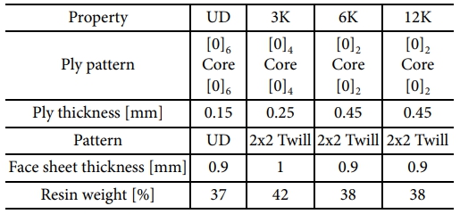
The sandwich composites investigated in this study were fabricated through a one-shot co-curing process [8], in which the CFRP face sheets and PVC foam core was cured simultaneously. Four types of epoxy-based CFRP prepregs UD tape and 3K, 6K, and 12K woven fabrics were employed as face sheet materials. These prepregs were selected to examine how differences in fiber architecture, areal weight, and resin distribution influence the formation and mechanical behavior of the interface. Their key material characteristics, including ply thickness, fiber pattern, and resin content, are summarized in Table 1. Variations in fiber alignment and weave geometry lead to different resin flow and infiltration behaviors during curing, thereby affecting the microstructure and mechanical integrity of the bonded interface.
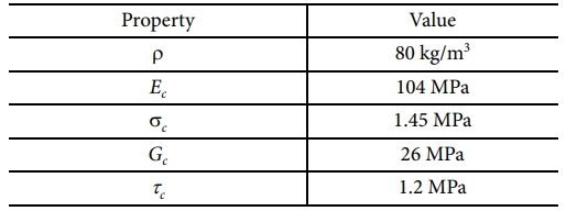
The core material used in the sandwich structure was a closed-cell PVC foam (Airex C70.75, 5 mm thickness, 80 kg/m³ density). This foam exhibits uniform density and cell morphology, enabling stable pressure transmission during curing and minimizing defects such as cell collapse or surface dimpling. Its continuous cell structure 3 facilitates controlled resin infiltration, contributing to consistent interface formation when co-cured with CFRP face sheets. These properties make PVC foam well suited for investigating interfacial behavior under reproducible processing conditions.
2.2 Tensile Test
Flatwise tensile tests were conducted in accordance with ASTM C297/C297M to evaluate the interfacial bond strength of CFRP/PVC foam core sandwich composites [9]. Eight configurations were defined based on the CFRP face sheet type (UD, 3K, 6K, and 12K) and the presence or absence of adhesive film, with five specimens prepared for each condition, resulting in a total of 40 specimens. Composite panels measuring 240 × 240 mm were fabricated and machined into 25 × 25 mm tensile coupons. Metal loading blocks were bonded to both ends of each specimen to ensure proper load transfer, and a custom jig was used to apply pure tensile loading. All tests were performed using a universal testing machine under displacement control at a rate of 0.5 mm/min, while load–displacement responses were continuously recorded to characterize interfacial bonding behavior.
2.3 FEA Simulations Set Up
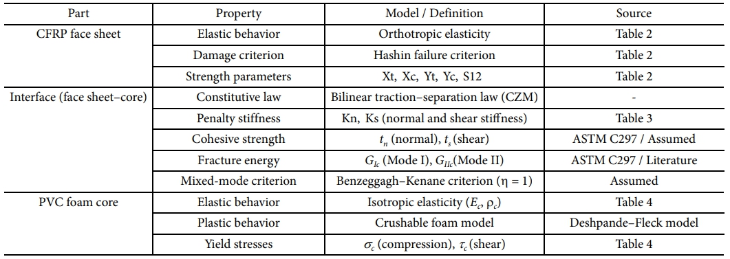
The numerical investigation was carried out using the commercial finite element software Abaqus, with the sandwich composite specimens modeled in compliance with the ASTM C297 testing configuration. The CFRP face sheets were represented as multilayered orthotropic elastic materials, and damage initiation and progression in the fibers and matrix under both tensile and compressive loading were captured using the Hashin failure criterion.
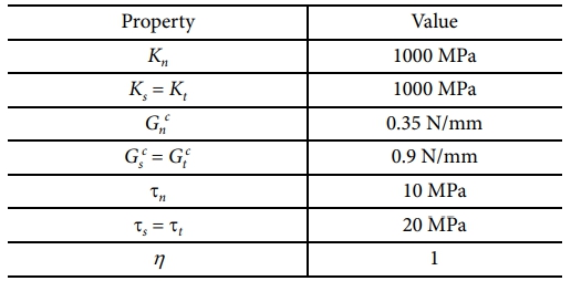
The PVC foam core was modeled as an isotropic elastic material based on manufacturer-provided properties, supplemented by a crushable foam constitutive model to accurately describe its compressive and shear responses as well as the associated failure behavior. The interaction between the face sheets and the core was simulated using a cohesive zone approach governed by a traction–separation relationship. For specimens fabricated without an adhesive film, the normal cohesive strength and Mode-I fracture energy were directly calibrated from the experimental results of the ASTM C297 flatwise tensile tests. Although the ASTM C297 test is intended to impose Mode-I–dominant loading, local interfacial shear stresses inevitably develop due to the elastic mismatch between the CFRP face sheets and the foam core, which can be captured through finite element analysis. Accordingly, mixed-mode damage evolution at the interface was defined using the Benzeggagh–Kenane criterion.
Since the ASTM C297 flatwise tensile test provides interfacial properties primarily under Mode-I–dominant loading conditions, the mixed-mode cohesive parameters employed in this study were not identified as intrinsic Mode-II fracture properties. The tangential (Mode-II) cohesive strength and fracture energy were assigned based on commonly adopted assumptions and representative literature values for polymer-based composite interfaces, solely to enable stable numerical simulation under combined normal and shear loading conditions. Therefore, the present cohesive formulation is intended to assess interfacial reliability under tensile loading rather than to extract intrinsic Mode-II or mixed-mode interfacial fracture toughness.
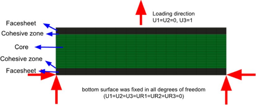
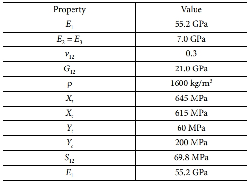
In terms of boundary conditions, the bottom surface of the lower face sheet was rigidly fixed, while a prescribed displacement was applied to the top surface of the upper face sheet to replicate the experimental loading condition. Both the face sheets and the core were discretized using eight-node reduced-integration solid elements (C3D8R), whereas the interface region was modeled with three-dimensional cohesive elements. The complete finite element model consisted of 8,092 elements in total. Detailed material properties employed in the simulations are summarized in Tables 2–4, and the applied boundary and loading conditions are schematically illustrated in Fig. 1.
It should be noted that the finite element model was developed and quantitatively validated primarily for the UD configuration, which exhibited the most critical interfacial behavior in the experimental observations. Accordingly, the predictive capability of the present modeling approach is limited to UD-based sandwich specimens, and direct extension of the current model to woven CFRP face sheet configurations is beyond the scope of this study.
2.4 Three-point Bending Test
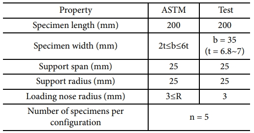
Three-point bending experiments were carried out to investigate the flexural response and interfacial integrity of the sandwich composite structures, following the procedures specified in ASTM C393/C393M [10]. This test method is commonly employed to characterize the coupled mechanical behavior of the face sheets, core material, and their interface when subjected to combined loading modes. The detailed specimen dimensions and three-point bending test configuration, including the support span, loading nose radius, support radius, and number of specimens per configuration, are summarized in Table 6.
All bending tests were conducted using a universal testing machine fitted with a dedicated three-point bending fixture. The specimen geometry, support span, and loading configuration were strictly defined in accordance with the ASTM standard. To avoid highly localized loading, the applied force was introduced through an aluminum loading block with a length of 20 mm positioned at the mid-span of the specimen, enabling a more evenly distributed contact. Matching aluminum blocks of the same length were placed at both supports to promote uniform load transmission and to reduce stress concentration effects at the contact regions.
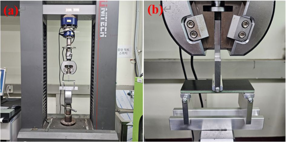
In compliance with ASTM C393/C393M guidelines, the loading rate was selected such that specimen failure would occur within a target duration of 3–6 minutes. Accordingly, a constant crosshead displacement rate of 6 mm/min was applied, resulting in fracture times of approximately 4–5 minutes for all specimens, thereby satisfying the standard requirements. During each test, load and displacement data were continuously recorded. Fig. 2 presents the experimental setup for the three-point bending test, where Fig. 2(a) shows an overall view of the testing configuration mounted on the universal testing machine, and Fig. 2(b) provides a detailed view of the loading nose and support fixture in contact with the specimen.
|
Fig. 1 Boundary and loading conditions |
|
Fig. 2 Three-point bending test ASTM C393/C393 M: (a) overall experimental configuration, (b) detailed view of the loading nose and support fixture. |
3.1 Tensile Test Result
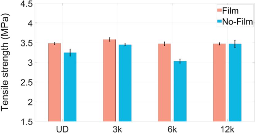
The mean interfacial tensile strength varied significantly with both the face sheet architecture and the use of an adhesive film, and the corresponding strength values for each configuration are reported in Fig. 3. In all specimens manufactured with an adhesive layer, failure consistently occurred within the core material irrespective of the face sheet type, indicating that the interface strength exceeded that of the foam core and that a reliable bonding condition was achieved.
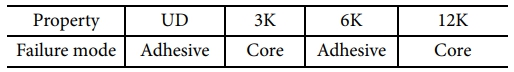
The post-test failure characteristics are summarized in Table 7. For adhesive-free specimens with 3K and 12K woven CFRP face sheets, failure occurred predominantly through CFRP face sheet fracture without interfacial debonding, demonstrating effective load transfer and sufficient interfacial bonding strength even in the absence of an adhesive film. In contrast, interfacial separation along the skin–core boundary was observed only in UD- and 6K-related configurations, indicating comparatively weaker interfacial bonding in these cases. This behavior is attributed to differences in fiber architecture and resin distribution at the interface region, which can influence local stress transfer and bonding effectiveness.
3.2 FEA Simulations Results
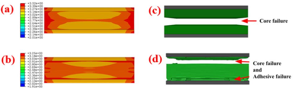
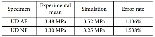
The numerical results for the UD specimens are presented in Fig. 4, where the UD specimen without adhesive film (UD–NF, Fig. 4(d)) exhibited a fracture pattern that closely reproduced the failure behavior observed in the experiments. The simulated tensile strengths of the UD specimens with and without adhesive film (UD–AF and UD–NF) are summarized in Table 8. The differences between the numerical predictions and the experimental measurements were very small, with error rates of 1.136% for UD–AF and 1.538% for UD–NF, demonstrating that the numerical model is capable of accurately predicting both the tensile strength and failure response of the UD-based adhesive-free sandwich specimens.
3.3 Three-point Bending Test Results
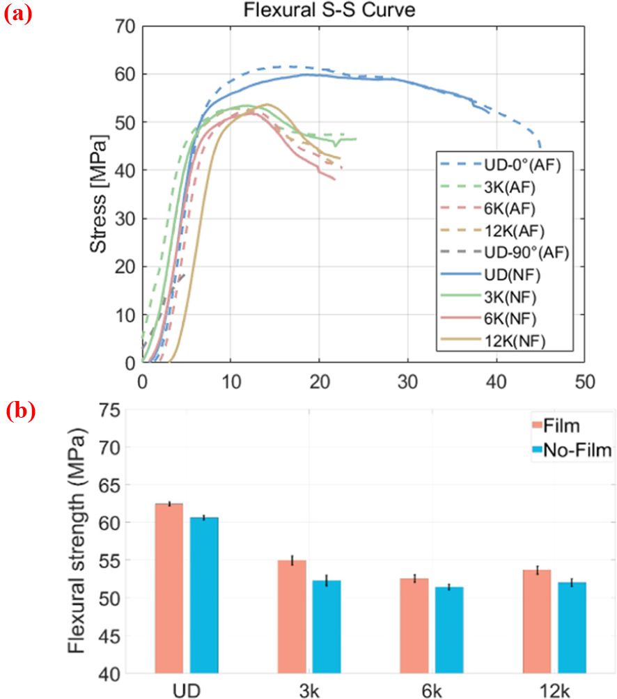
Three-point bending tests were performed in accordance with ASTM C393 to examine the flexural response of the sandwich structures, and the corresponding results are presented in Fig. 5. Regardless of the use of an adhesive film, all specimens exhibited a similar failure sequence in which initial compression of the core occurred beneath the loading point, followed by overall structural failure. With the exception of the UD configurations, most specimens demonstrated comparable maximum flexural load capacities, whereas the UD specimens withstood noticeably higher loads prior to failure.
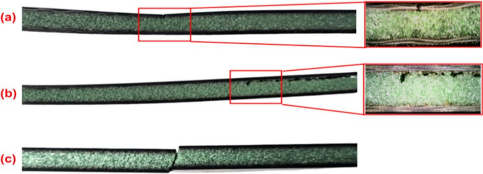
Fig. 5 compares the flexural stress–strain behavior and the maximum flexural strength of the fabricated specimens. Representative failure modes observed after bending tests are summarized in Fig. 6. For most configurations, failure was predominantly initiated by fracture of the upper CFRP face sheet and/or core compression beneath the loading point.
Interfacial delamination during three-point bending was observed only in specific UD configurations, particularly in the adhesive-free UD specimens with a 90° fiber orientation (UD NF 90°), and occurred under relatively high flexural load levels. This behavior is attributed to the increased stiffness associated with the 90° fiber orientation relative to the loading direction, which reduced overall deformation and led to localized stress concentrations at the face sheet–core interface, thereby increasing susceptibility to interfacial failure.
To further validate this interpretation, additional bending tests were conducted using the same UD material with a 0° fiber orientation. In this case, the measured flexural strength was significantly reduced to 27.21 MPa, and a mixed-mode failure involving simultaneous fracture of both the face sheet and the core was observed.
These findings indicate that under flexural loading conditions, CFRP face sheets with thicknesses below 1 mm possess lower tensile or buckling resistance than the interfacial bonding strength. Accordingly, the bonding reliability of the adhesive-free 3K and 12K specimens with sub-1 mm face sheets was verified through cross-comparison with ASTM C297 flatwise tensile test results, confirming that sufficient structural performance can be achieved even in the absence of an adhesive film.
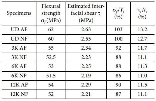
To quantitatively support this conclusion, a simplified assessment based on classical sandwich beam theory was conducted using the experimentally measured peak loads. The maximum face-sheet bending stress sf and the interfacial (core) shear stress ti were estimated and normalized by the corresponding material strengths, namely the CFRP transverse tensile strength Yt and the interfacial shear strength ts. The ratio sf/Yt represents the proximity of the nominal face-sheet bending stress to the material strength, while the ratio ti/ts provides a dimensionless measure of how close the interfacial shear stress is to the interfacial shear capacity.
For a three-point bending configuration, the maximum face-sheet bending stress was estimated using the ASTM C393 formulation as
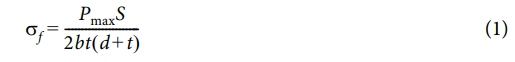
where Pmax is the experimentally measured peak load, S is the support span, b is the specimen width, t is the face-sheet thickness, and d is the core thickness.
The interfacial (core) shear stress was approximated by assuming a uniform shear stress distribution across the core thickness, yielding
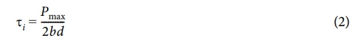
As summarized in Table 9, the estimated face-sheet stresses calculated using Eq. (1) reached approximately 86–103% of the CFRP strength, whereas the estimated interfacial shear stresses calculated using Eq. (2) remained only about 11–13% of the interfacial shear strength. It should be noted that the estimated face-sheet stress represents an average bending stress over the cross-section, and that local stress concentrations or compressive micro-buckling in the thin CFRP face sheets may trigger face-sheet failure before the nominal stress reaches the material strength. This quantitative comparison confirms that flexural failure was governed by face-sheet and core failure rather than by Mode-II interfacial shear fracture.
|
Fig. 3 Tensile test result |
|
Fig. 4 Numerical simulation results of UD specimens under ASTM C297 tensile loading: (a) Stress distribution of UDAF specimen, (b) Deformed shape of UD-AF specimen, (c) Stress distribution of UD-NF specimen, (d) Deformed shape of UD-NF specimen |
|
Fig. 5 Maximum flexural strength: (a) Flexural S-S curve (b) Flexural strength |
|
Fig. 6 Representative failure modes observed in flexural tests: (a) Top face sheet failure (Photo is 12K), (b) Interfacial delamination at specimen edge (UD NF 90°), (c) Combined failure of skin and core (UD AF 0°) |
|
Table 9 Quantitative comparison of face-sheet bending stress and interfacial shear stress under three-point bending |
This study is a follow-up to previous research on CFRP/PVC foam core sandwich composites manufactured using an adhesive-free co-curing process, in which tensile testing and ultrasonic non-destructive evaluation were performed. In the present work, additional experimental and numerical investigations were conducted to further assess the mechanical behavior and interfacial reliability of these structures, including finite element analysis and three-point bending tests aimed at comprehensively validating the structural feasibility of eliminating the adhesive layer. The finite element model developed based on the ASTM C297 test configuration showed excellent agreement with the experimental results, with tensile strength prediction errors within 2% for the UD specimens, confirming that the analysis approach employing a cohesive zone model calibrated with experimentally derived interfacial properties can reliably capture the interfacial behavior and failure characteristics of adhesive-free sandwich structures under tensile loading conditions.
Results from the three-point bending tests conducted in accordance with ASTM C393 indicated that, regardless of the presence of an adhesive film, failure was predominantly governed by core compression and/or face sheet failure beneath the loading point for most configurations, and that Mode-II–related interfacial shear effects induced during bending did not govern the overall failure response. Except for the UD specimens, the maximum flexural strengths were comparable across all configurations, while limited interfacial delamination was observed only in specific UD configurations under relatively high flexural load levels, a behavior attributed to increased stiffness associated with fiber orientation leading to localized stress concentration at the face sheet–core interface.
A simplified quantitative assessment based on classical sandwich beam theory further demonstrated that the estimated face-sheet bending stresses reached approximately 86–103% of the CFRP strength, whereas the estimated interfacial shear stresses remained only about 11–13% of the interfacial shear strength obtained from ASTM C297 tests. It is noted that the estimated face-sheet stress represents an average bending stress, and that local stress concentrations or compressive micro-buckling in the thin CFRP face sheets may trigger face-sheet failure before the nominal stress reaches the material strength.
Overall, the findings demonstrate that for sandwich structures with CFRP face sheets thinner than 1 mm, the structural response under flexural loading is governed more by the mechanical limits of the face sheets and core than by interfacial Mode-II fracture, and that adhesive-free sandwich composites incorporating 3K and 12K woven face sheets exhibit sufficient interfacial reliability and structural performance, as confirmed through cross-validation of flatwise tensile and bending test results. Importantly, the present study does not aim to extract intrinsic Mode-II interfacial fracture properties, but rather to assess interfacial reliability under flexural loading conditions where Mode-II–related interfacial shear stresses may be present but are not governing.
Future work will focus on conducting fatigue and impact tests to further verify the structural integrity of adhesive-free sandwich structures for unmanned aerial vehicle applications, demonstrating that the elimination of adhesive films does not compromise long-term durability or impact resistance, even under service conditions where Mode-II–type interfacial shear loading may be present.
This work was supported by the Korea Institute of Energy Technology Evaluation and Planning(KETEP) and the Ministry of Climate, Energy & Environment(MCEE) of the Republic of Korea (RS-2024-00449355).
- 1. Jang, W.C., and Roh, H.D., “Sandwich Composites Manufacturing: A Review of Materials, Methods, Applications and Challenges,” International Journal of Precision Engineering and Manufacturing, Vol. 26, 2025, pp. 2093-2109.
-

- 2. Ainin, F.N., Azaman, M.D., Abdul Majid, M.S., and Ridzuan, M.J.M., “Low-velocity impact behavior of sandwich composite structure with 3D printed hexagonal honeycomb core: varying core materials,” Functional Composites and Structures, Vol. 4, No. 3, 2022, Article No. 035007.
-
- 3. Gülcan, O., Günaydın, K., and Tamer, A., “The effect of geometrical parameters on blast resistance of sandwich panels—a review,” Functional Composites and Structures, Vol. 5, No. 2, 2023, Article No. 022001.
-
- 4. Jeong, W.J., Yang, S.H., Jang, W.C., Shim, Y., Hwang, S.-H., and Roh, H.D., “Manufacturing Debonding Study of PVC/Foam Core Sandwich Composites by Ultrasonic A-Scan,” Composites Research, Vol. 38, No. 4, 2025, pp. 458–467.
-
- 5. Fal, M., Meinders, R., Okanmisope, F., Chandrashekhara, K., Alabdulmuhsin, A., Alotaibi, A., and Alqahtani, S., “Experimental and numerical study of increased core surface area on the performance of additively manufactured honeycomb sandwich structures,” Functional Composites and Structures, Vol. 6, No. 2, 2024, Article No. 025008.
-
- 6. CMH-17: Wichita State. Composite Materials Handbook. Vol. 6. Structural Sandwich Composites. SAE International, 2013
- 7. Jung, Y.-T., Roh, H.D., Lee, I.-Y., and Park, Y.-B., “Strain sensing and progressive failure monitoring of glass-fiber-reinforced composites using percolated carbon nanotube networks,” Functional Composites and Structures, Vol. 2, No. 1, 2020, Article No. 015006.
-
- 8. Zenkert, D.,The handbook of sandwich construction. Engineering Materials Advisory Services, 1997.
- 9. ASTM International. ASTM C297/C297M: Standard Test Method for Flatwise Tensile Strength of Sandwich Constructions. ASTM International, 2016.
-
- 10. ASTM. C393/C393M-20, Standard Test Method for Core Shear Flexural Properties of Sandwich Constructions by Beam Flexure. West Conshohocken, PA: ASTM International; 2020.
-
 This Article
-
2026; 39(1): 53-59
Published on Feb 28, 2026
- 10.7234/composres.2026.39.1.053
- Received on Jan 18, 2026
- Revised on Feb 2, 2026
- Accepted on Feb 12, 2026
Services
- Abstract
1. introduction
2. experimental setup
3. result and discussion
4. conclusions
- Acknowledgements
- References
- Full Text PDF
Shared
Correspondence to
- Hyung Doh Roh
-
Department of Mechanical Engineering and BK21 Four ERICA-ACE Center
- E-mail: rhd1213@hanyang.ac.kr
Gangnam Mirae Tower, Suite 601, 174 Saimdang-ro, Seocho-gu, Seoul 06627, South Korea
Tel: +82-2-598-1550 Fax: +82-2-598-1557 E-mail: composites@kscm.re.kr