







- Additively Manufactured Fiber-Reinforced Composite-Integrated Curved Dual-Band Conformal Antenna for UAV Winglet Applications
Tomasz Korgul*, Dong-Jin Park*, Do-Hyeon Jin*, Jung-Ryul Lee*†
* Department of Aerospace Engineering, Korea Advanced Institute of Science and Technology
This article is an open access article distributed under the terms of the Creative Commons Attribution Non-Commercial License (http://creativecommons.org/licenses/by-nc/4.0) which permits unrestricted non-commercial use, distribution, and reproduction in any medium, provided the original work is properly cited.
This paper reports the design and experimental validation of a curved dual-band conformal antenna integrated into an additively manufactured fiber-reinforced composite UAV winglet module. A curvature-matched microstrip patch is optimized through full-wave simulation and embedded within a lightweight composite shell designed to preserve the local leading-edge geometry. The final prototype is characterized by return-loss and far-field measurements in an anechoic environment, confirming dual-band impedance matching and forward-directed radiation suitable for wireless communication links.
Keywords: Conformal antenna, Fiber-reinforced composite, Additive manufacturing, Dual-band patch, Robotic measurement
The aerospace sector is moving toward lightweight multifunctional structures that combine mechanical support with sensing, communication, and embedded electronics [1–3]. Smart composite structures are particularly attractive for this purpose because continuous fiber-reinforced materials can provide high specific stiffness and strength while enabling additional functions such as structural health monitoring, wireless communication, and embedded diagnostics [4–6]. In this context, electromagnetic–structural smart-skin concepts have received increasing attention as a route for integrating antenna systems directly into aircraft composite structures [7].
For wireless structural health monitoring (SHM), embedded sensing nodes require a reliable radio-frequency interface for transmitting diagnostic data while reducing wiring complexity [8–10]. Conventional external antennas may increase aerodynamic drag, require additional mounting hardware, and remain exposed to impact, vibration, and environmental damage. Conformal antennas provide a low-profile alternative by following the curvature of the host structure and preserving a smooth aerodynamic surface [11–13]. These features are especially important for UAV platforms, where mass, volume, and aerodynamic penalties must be minimized.
Previous studies have explored several approaches for integrating antennas into curved or composite aerospace structures. Conformal microstrip antennas have been investigated for aircraft fuselage and UAV surfaces to reduce protrusions and preserve aerodynamic shape [11–13]. In parallel, conformal load-bearing antenna structures (CLAS) have been studied as multifunctional smart-skin concepts in which radiating elements and feed structures are embedded within composite sandwich panels or aircraft skin structures [14–18]. Additive manufacturing has also been introduced as an enabling route for fabricating conformal antenna-support structures and embedding RF functionality into complex curved geometries [19]. In addition, compact dual-band and multi-band antennas operating around 2.4 GHz and 5–6 GHz have been reported for UAV, Wi-Fi, and wireless communication applications [20–22].
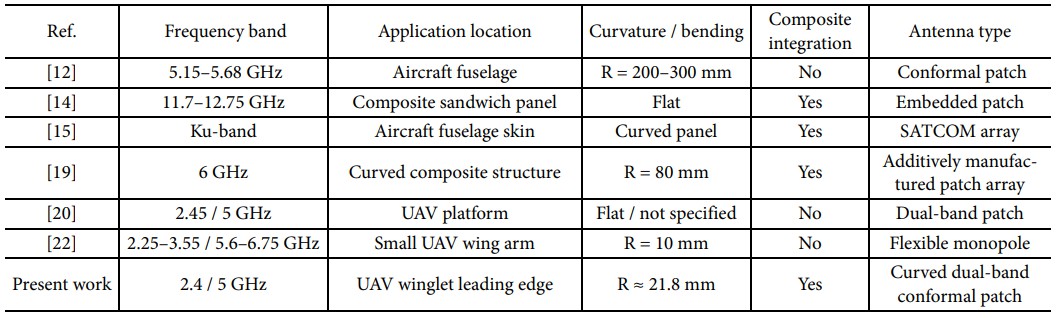
To clarify the novelty of the present study, Table 1 compares representative conformal, composite-integrated, additively manufactured, and UAV-oriented antenna studies. The comparison focuses on application location, curvature, and composite integration, because these factors strongly affect the antenna geometry, packaging constraints, and feasibility of aerodynamic embedding.
As summarized in Table 1, previous studies have addressed conformal aircraft antennas, composite-embedded antennas, additively manufactured conformal antennas, and dual-band UAV antennas. However, these features are usually demonstrated separately. Previous composite-integrated antenna studies mainly focus on flat sandwich panels or large aircraft skin structures, while additively manufactured conformal antenna studies are generally single-band or not targeted toward compact UAV winglet integration. In contrast, compact dual-band UAV antennas are usually implemented as flat, flexible, or surface-mounted antennas rather than as embedded modules within a fiber-reinforced composite aerodynamic component. In addition, many previous studies report antenna validation using return-loss measurements and selected radiation-plane cuts, whereas the present work evaluates the assembled prototype using a robotic electromagnetic measurement system and hemispherical 3D radiation-pattern characterization at 5 GHz. This provides a more complete assessment of the radiation behavior after integration into the curved composite module.
This paper reports the design, fabrication, and experimental validation of a curved dual-band conformal antenna intended for integration into a composite UAV winglet leading edge. A curvature-matched microstrip patch is optimized using full-wave simulation and embedded within an additively manufactured fiber-reinforced composite shell. The novelty of this work is the demonstration of a compact, installation-oriented antenna prototype that combines: (i) dual-band 2.4/5 GHz operation, (ii) a specific UAV winglet leading-edge application location, (iii) high-curvature conformal integration with a radius of approximately 21.8 mm, (iv) embedding within a fiber-reinforced composite module, and (v) experimental validation of the final assembled prototype using return-loss measurement and robotic hemispherical far-field radiation characterization. The present study focuses on electromagnetic design, fabrication, and antenna-performance validation; quantitative structural load-bearing assessment of the assembled module is outside the scope of this work.
2.1 Design and fabrication
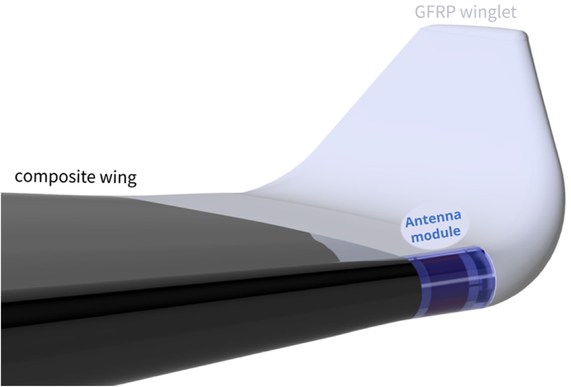
The proposed curved dual-band conformal antenna module was developed for integration into a UAV winglet leading edge to enable a fully embedded radiating aperture while maintaining a smooth aerodynamic surface (Fig. 1). The module follows the local leading-edge curvature and is designed to support wireless communication in the 2.4 and 5 GHz ISM bands. The overall conformal envelope has a footprint of 64 mm (length, L) × 43 mm (width, W) with a curvature radius of approximately 21.8 mm. The total thickness is constrained by the aerodynamic shell and ranges from 7.88 to 8.44 mm. The curved antenna layer (patch–substrate–ground) has a thickness of 1.57 mm, and the assembled module mass is 41 g. The final thickness was determined not only by the aerodynamic envelope but also by additive-manufacturing constraints, including the minimum printable wall thickness, the required space for continuous-fiber placement, and the clearance needed for the right-angle SMA feed connector inside the housing.
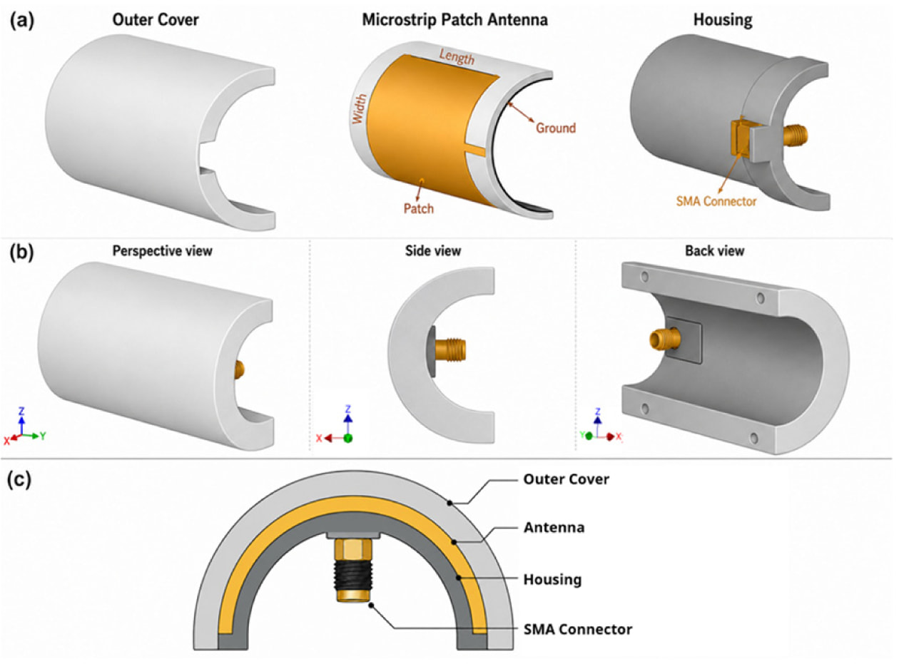
The antenna module consists of three functional components: (i) a fiber-reinforced composite outer cover that preserves the external aerodynamic contour, (ii) an internal housing that defines the cavity and supports the feed interface, and (iii) a curved microstrip antenna layer (Fig. 2). Additive manufacturing was selected because the winglet leading edge has a compact and highly curved geometry that is difficult to realize using conventional flat-laminate fabrication. The process also enables accurate reproduction of the curvature-matched shell, integration of internal assembly features, local fiber reinforcement, and repeatable fabrication of the curved antenna-support structure.
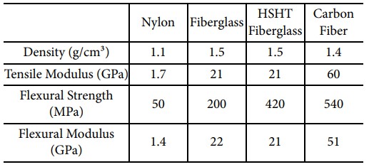
The structural components were fabricated using a Markforged X7 continuous-fiber composite 3D printer, which uses separate nozzles for polymer deposition and continuous-fiber reinforcement. This process was selected because it enables repeatable fabrication of compact curved parts, local reinforcement of selected regions, and integration of internal assembly features required for the antenna housing and feed interface. Nylon was used for the antenna housing and curved dielectric substrate because of its printability, dimensional stability, and relatively low dielectric constant. The outer cover was printed as a nylon matrix reinforced with continuous HSHT fiberglass. HSHT fiberglass was selected instead of carbon-fiber reinforcement because glass-fiber reinforcement is electrically nonconductive and therefore more suitable for RF-transparent structures with embedded antenna elements. Compared with standard fiberglass, HSHT fiberglass provides improved mechanical performance, especially higher flexural strength, while maintaining a comparable dielectric-property range. Therefore, the nylon/HSHT fiberglass combination provides a practical compromise between electromagnetic compatibility, curvature stability, and mechanical support.
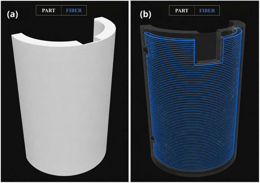
As shown in Fig. 3, two internal continuous-fiber reinforcement layers were assigned within the curved outer cover to reinforce the shell around the embedded antenna module. The figure is a schematic visualization of the fiber distribution and does not represent the exact number of individual fiber strands or their actual thickness. The material properties used for material selection are summarized in Table 2.
The radiating patch and ground plane were implemented using adhesive copper tape applied to the curved nylon substrate. The antenna was excited using a right-angle SMA coaxial feed connector inserted through the printed housing. The inner conductor of the SMA connector was connected to the radiating patch, while the outer conductor was referenced to the ground plane. This configuration provides a compact and mechanically supported feed interface compatible with the embedded curved geometry.
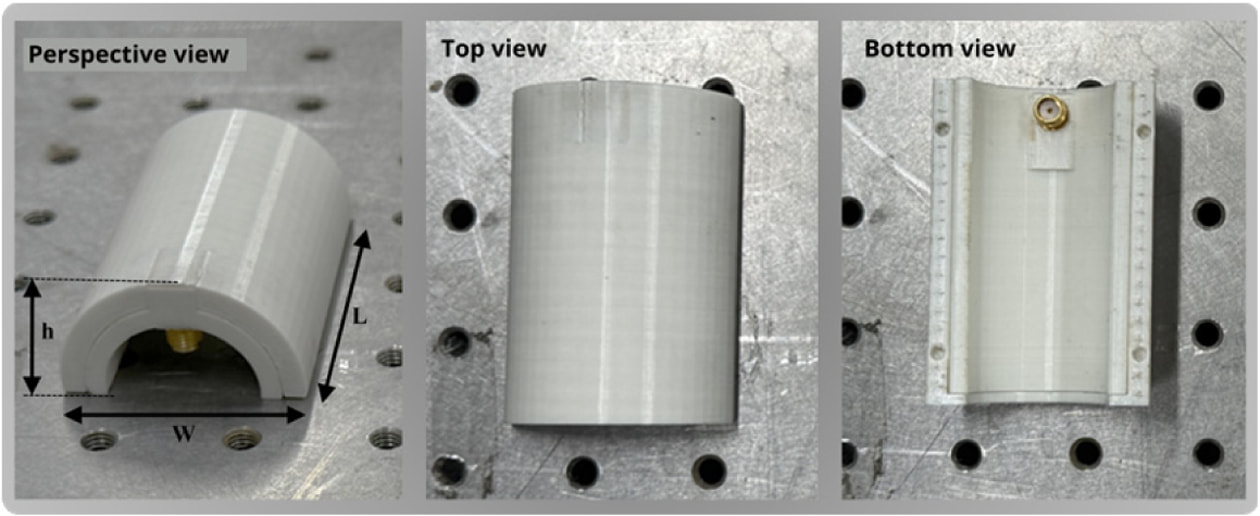
Assembly was performed by first installing the right-angle SMA connector into the printed housing, then mounting the curved antenna layer onto the housing, and finally closing the cavity with the fiber-reinforced composite outer cover. The final configuration forms a compact composite-integrated conformal antenna module suitable for UAV winglet leading-edge installation (Fig. 4). It should be noted that the material properties and reinforcement layout support the material-selection and structural-integration rationale; however, quantitative structural load-bearing testing of the assembled module is outside the scope of the present study.
2.2 Simulation and measurement methods
The initial dimensions of the curved microstrip patch antenna were estimated using conventional rectangular microstrip patch design equations. The patch width W and patch length L, used as the main design variables, are defined in Fig. 2(a). Although these equations are derived for planar single-band patches, they provide useful starting values for full-wave optimization. The initial patch width (W) was estimated as

where c is the speed of light, fr is the target resonant frequency, and εr is the relative permittivity of the substrate. The effective dielectric constant was calculated as

where h is the substrate thickness. The fringing-field extension length DL was estimated using
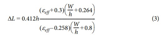
The effective patch length (Leff) and physical patch length (L) were then calculated as
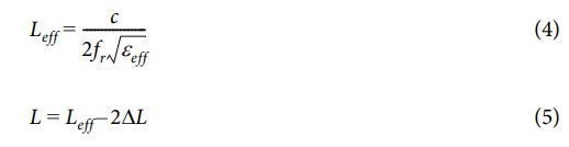
These analytical values were used only as the initial design estimate. Because the final antenna is curved, dual-band, and embedded within a printed composite module, the final geometry was obtained through full-wave electromagnetic optimization.
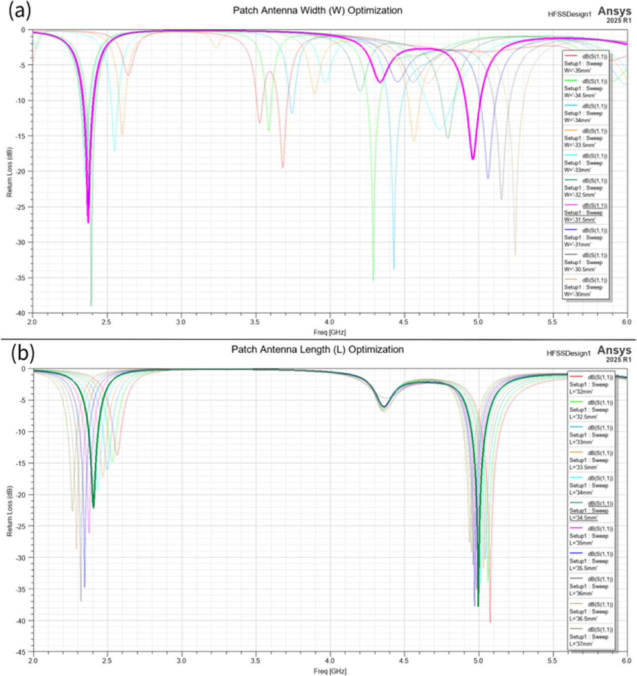
Full-wave electromagnetic simulations were carried out in Ansys HFSS to optimize the dual-band response of the composite-integrated conformal antenna module under the target winglet curvature and surrounding printed structure. The simulation model included the curved nylon substrate, adhesive copper patch and ground plane, printed nylon housing, and fiber-reinforced outer cover to capture the dielectric loading and cavity effects introduced by the embedded configuration. The patch width and length were parameterized and iteratively adjusted to achieve a return loss of less than −10 dB near the 2.4 GHz and 5 GHz ISM bands. The final optimized patch dimensions were W = 31.5 mm and L = 34.5 mm. Representative parametric results for patch-width and patch-length tuning are shown in Fig. 5.
The electromagnetic model was used to evaluate both impedance matching and radiation behavior. The return-loss response was simulated over the 2–6 GHz frequency range to cover both operating bands and possible detuning regions caused by structural embedding. The simulated radiation pattern was also evaluated at 5 GHz (Fig. 8) to confirm the forward-directed radiation behavior required for the UAV winglet leading-edge application.
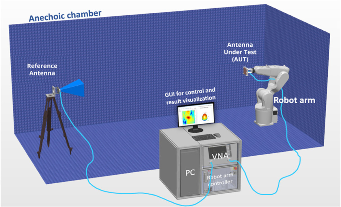
Experimental validation was performed in an anechoic chamber using a vector network analyzer for S-parameter acquisition and a robotic antenna-measurement system for far-field characterization (Fig. 6). Return loss (S11) was measured over the 2–6 GHz frequency range to verify dual-band impedance matching. Radiation characteristics were measured at 5 GHz by scanning the antenna under test over a hemispherical angular range while maintaining a fixed antenna orientation and a constant stand-off distance of R = 6 m from the reference antenna. This distance satisfies the far-field condition at the measured frequency.
The realized gain of the antenna under test was obtained using the gain-transfer method. The measured transmission coefficient S21 was converted to antenna gain using

where GAUT is the realized gain of the antenna under test, Gref is the gain of the reference antenna, (R) is the stand-off distance between the reference antenna and the antenna under test, l is the free-space wavelength, and S21 is the measured transmission coefficient in dB. This formulation was applied consistently to the measured radiation data to obtain the angular gain distribution at 5 GHz.
In the present study, far-field radiation characterization was performed at 5 GHz as a representative upper-band validation because the robotic measurement setup and reference antenna configuration were optimized for this frequency range. The 2.4 GHz band was validated through return-loss measurement, while full 2.4 GHz radiation-pattern characterization was not included in the present work. This limitation is considered in the discussion of the dual-band antenna performance.
Differences between simulated and measured results may arise from practical fabrication and measurement uncertainties, including dielectric-property variation of the printed nylon and fiber-reinforced cover, copper-tape alignment tolerance on the curved substrate, SMA feed-connector implementation, small air gaps between the antenna layer and housing, and alignment errors in the robotic far-field measurement setup. These factors were considered when interpreting the simulation–experiment agreement.
|
Fig. 1 Leading-edge antenna-module integration concept |
|
Fig. 2 Composite-integrated conformal antenna module structure: (a) exploded view, (b) full assembly, and (c) cross-sectional view |
|
Fig. 3 Continuous-fiber additive-manufacturing layout of the outer cover: (a) printed cover geometry and (b) schematic visualization of the continuous HSHT fiberglass distribution assigned as two internal reinforcement layers within the curved shell region. The fiber paths are shown schematically and do not indicate the exact number or thickness of individual fibers |
|
Fig. 4 Fabricated composite-integrated conformal antenna module shown in different views. The perspective view indicates the module length (L), width (W), and height (h), while the bottom view shows the housing and right-angle SMA feed connector |
|
Fig. 5 Parametric optimization results in Ansys HFSS: (a) effect of patch-width variation on return loss and (b) effect of patch-length variation on return loss |
|
Fig. 6 Anechoic-chamber measurement setup for electromagnetic characterization of the composite-integrated conformal antenna module using a vector network analyzer (VNA), reference antenna, and robotic positioning system |
|
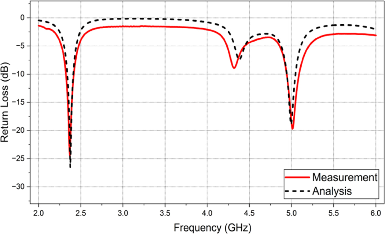
Fig. 7 Return-loss performance of the composite-integrated conformal antenna module: comparison between fullwave simulation and measurement |
|
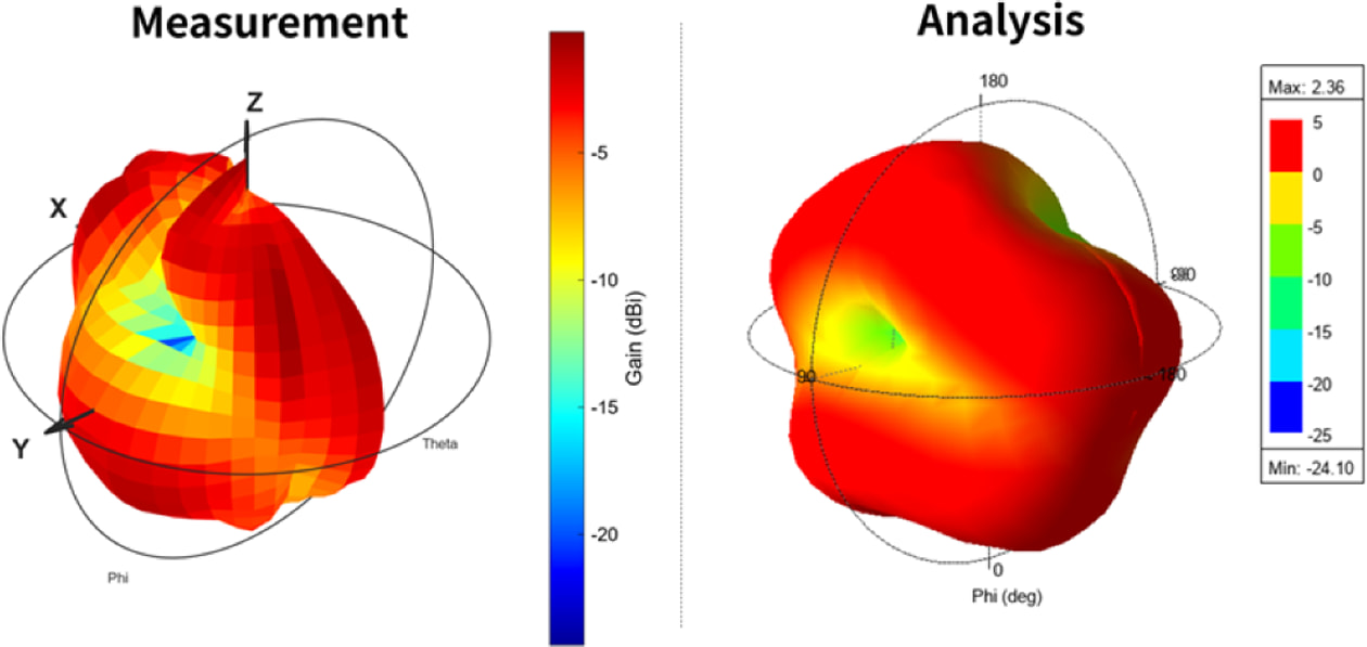
Fig. 8 Three-dimensional radiation patterns of the compositeintegrated conformal antenna module at 5 GHz: comparison between measurement and simulation/analysis |
3.1 Impedance matching and bandwidth
Figure 7 compares the simulated and measured return loss of the final composite-integrated conformal antenna module. Two resonances are observed, corresponding to the lower 2.4 GHz band and the upper 5 GHz band. The measured response shows close agreement with the full-wave simulation, indicating that the design and tuning procedure can predict the antenna behavior under the target curvature and embedded composite-module configuration.
The measured lower-band resonance occurs at 2.37 GHz, compared with 2.375 GHz in simulation. This corresponds to a very small frequency difference of approximately 5 MHz. The measured −10 dB bandwidth in the lower band is 2.325–2.415 GHz, corresponding to approximately 90 MHz. In the upper band, the measured resonance occurs at 5.01 GHz, compared with 4.995 GHz in simulation, giving a difference of approximately 15 MHz. The measured −10 dB bandwidth in the upper band is approximately 145 MHz. These results confirm that dual-band impedance matching is achieved after fabrication and assembly within the additively manufactured fiber-reinforced composite module.
The small differences between the simulated and measured responses are attributed to practical fabrication and assembly tolerances. Possible sources include uncertainty in the dielectric properties of the printed nylon and fiber-reinforced cover, small air gaps between the curved antenna layer and housing, alignment tolerance of the adhesive copper patch and ground plane on the curved substrate, and the practical implementation of the right-angle SMA feed connector. Despite these uncertainties, both measured resonances remain close to the simulated values and satisfy the −10 dB matching criterion, indicating that the embedded composite configuration produces predictable electromagnetic behavior.
3.2 Radiation pattern at 5 GHz
To verify the radiation behavior in the upper operating band, hemispherical far-field measurements were performed at 5 GHz for the final composite-integrated conformal antenna module. The measured radiation distribution shows a forward-biased radiation tendency, which is consistent with the intended UAV winglet leading-edge placement. Figure 8 presents the measured and simulated radiation patterns used to evaluate the overall radiation shape and directional behavior.
The measured radiation pattern follows the main trend predicted by simulation, including the forward-directed radiation region and the presence of lower-radiation regions caused by the curved geometry and embedded cavity configuration. Differences in absolute gain level and local pattern shape can be attributed to practical losses and uncertainties, including conductor loss from the adhesive copper layer, dielectric losses in the printed polymer and fiber-reinforced cover, SMA feed-connector loss, assembly tolerance, and alignment uncertainty in the robotic far-field measurement setup.
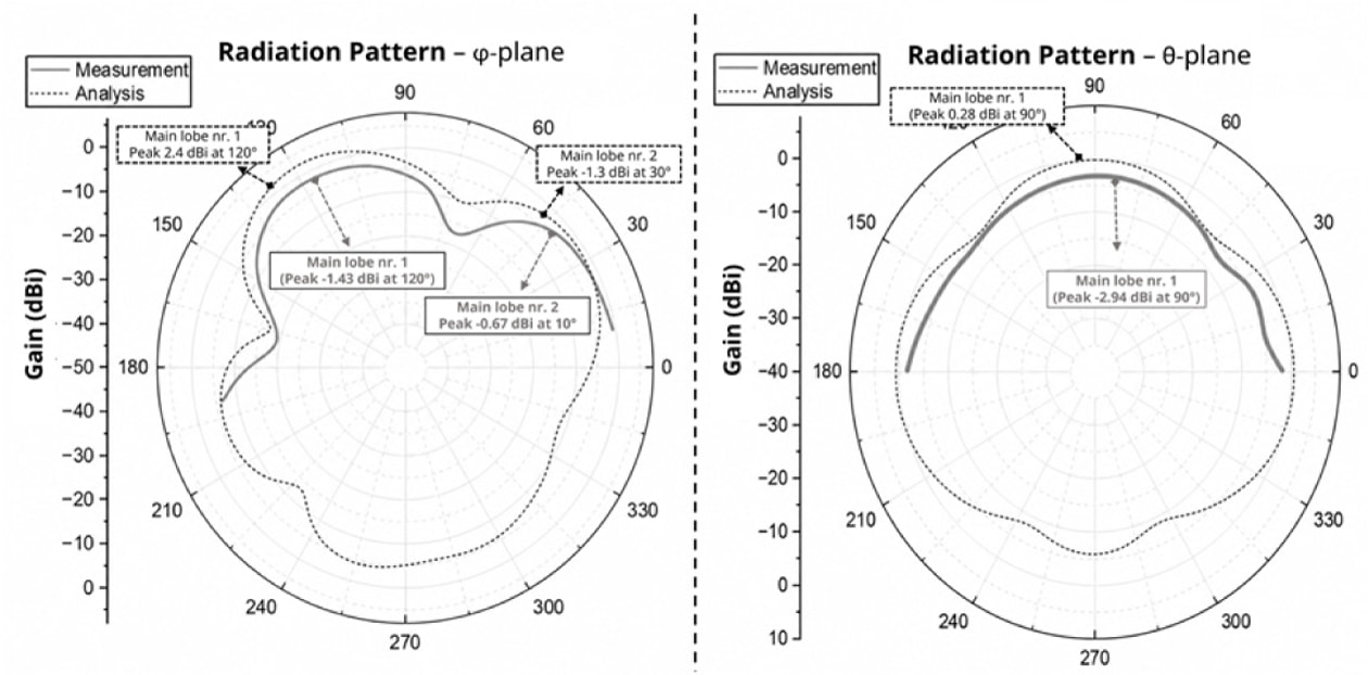
To further quantify the radiation behavior, two-dimensional gain cuts were extracted in the ϕ- and θ-planes, as shown in Fig. 9. In the ϕ-plane, the measured pattern exhibits two main radiation regions, with peak values of approximately −1.43 dBi at 120° and −0.67 dBi at 10°. The corresponding simulated peaks occur at approximately 2.4 dBi at 120° and −1.3 dBi at 30°. Although the absolute gain levels and peak angles are not identical, the measured and simulated results show a similar forward-biased radiation tendency.
In the θ-plane, both simulation and measurement show the main radiation direction around 90°. The measured peak gain is approximately −2.94 dBi, while the simulated peak is approximately 0.28 dBi. The lower measured gain is mainly attributed to practical losses and measurement uncertainties introduced by the embedded configuration, including the adhesive copper layer, printed dielectric materials, SMA feed implementation, small assembly gaps, and robotic alignment tolerance. Overall, the 2D radiation cuts support the 3D radiation results and confirm that the integrated conformal antenna module maintains directional radiation behavior at 5 GHz.
The 5 GHz radiation result confirms that the integrated antenna module maintains directional behavior suitable for a forward wireless link in the upper operating band. However, full radiation-pattern characterization was performed only at 5 GHz in the present study. The 2.4 GHz band was validated through return-loss measurement, but 2.4 GHz far-field radiation-pattern measurement was not included because the robotic measurement setup and reference-antenna configuration were optimized for the 5 GHz range. Therefore, the present radiation result should be interpreted as representative upper-band validation, while complete dual-band radiation characterization will be addressed in future work.
Overall, the results demonstrate that the proposed composite-integrated conformal antenna module achieves dual-band impedance matching and maintains forward-directed radiation behavior at 5 GHz after integration into the curved additively manufactured composite structure.
|
Fig. 9 Two-dimensional radiation-pattern cuts of the composite-integrated conformal antenna module at 5 GHz: measured and simulated gain distributions in the ϕ-plane and θ-plane |
A curved dual-band conformal antenna module for UAV winglet leading-edge integration was designed, fabricated, and experimentally validated. The proposed module combines an additively manufactured fiber-reinforced composite shell, consisting of nylon with continuous HSHT fiberglass reinforcement, with a curvature-matched microstrip patch implemented using adhesive copper layers on a curved nylon substrate. The structure was developed to preserve a smooth aerodynamic surface while enabling embedded wireless communication in the 2.4 GHz and 5 GHz ISM bands.
Full-wave simulations were used to tune the antenna geometry under the target curvature and surrounding printed structure. The measured return loss showed two resonances in close agreement with simulation, with resonances at 2.37 GHz and 5.01 GHz and −10 dB bandwidths of approximately 90 MHz and 145 MHz, respectively. These results confirm that dual-band impedance matching was maintained after fabrication and assembly within the additively manufactured composite module.
Far-field radiation measurements at 5 GHz confirmed directional behavior consistent with the intended winglet leading-edge installation. The measured and simulated two-dimensional radiation cuts showed similar forward-biased radiation tendencies, although differences in absolute gain level and local pattern shape were observed due to practical fabrication, material, feed, and measurement uncertainties. Since full radiation-pattern characterization was performed only at 5 GHz, the 2.4 GHz radiation response remains a limitation of the present study and will be addressed in future work.
Overall, the results demonstrate the feasibility of integrating a curved dual-band conformal antenna into an additively manufactured fiber-reinforced composite UAV winglet module. The main contribution of this work is the development and validation of a compact, installation-oriented antenna prototype that combines a specific winglet leading-edge location, high-curvature conformal geometry, composite-module integration, dual-band wireless functionality, and robotic hemispherical radiation-pattern characterization. The proposed workflow provides practical guidance for embedding RF functionality into compact, highly curved composite aerospace components while maintaining a flush aerodynamic form factor.
This research was supported by Unmanned Vehicles Core Technology Research and Development Program through the National Research Foundation of Korea (NRF) and Unmanned Vehicle Advanced Research Center (UVARC) funded by the Ministry of Science and ICT, the Republic of Korea (NRF 2020M3C1C1A01084220).
- 1. Sairajan, K.K., Aglietti, G.S., and Mani, K.M., “A Review of Multifunctional Structure Technology for Aerospace Applications,” Acta Astronautica, Vol. 120, 2016, pp. 30-42.
-

- 2. Behdinan, K., and Moradi-Dastjerdi, R., Advanced Multifunctional Lightweight Aerostructures: Design, Development, and Implementation, Wiley, 2021.
- 3. del Bosque, A., Vergara, D., and Fernández-Arias, P., “An Overview of Smart Composites for the Aerospace Sector,” Applied Sciences, Vol. 15, No. 6, 2025, p. 2986.
-
- 4. Pinto, F., Ciampa, F., Meo, M., and Polimeno, U., “Multifunctional SMArt Composite Material for in situ NDT/SHM and De-icing,” Smart Materials and Structures, Vol. 21, No. 10, 2012, p. 105010.
-
- 5. Dulal, M., Islam, M.R., Maiti, S., Islam, M.H., Ali, I., Abdelkader, A.M., Novoselov, K.S., Afroj, S., and Karim, N., “Smart and Multifunctional Fiber-Reinforced Composites of 2D Heterostructure-Based Textiles,” Advanced Functional Materials, Vol. 33, No. 23, 2023, p. 2305901.
-
- 6. Yi, X., Rudd, C., Liu, X., Hu, D., Jiang, M., Dong, C., and Liu, Z., “Development of Multifunctional Composites for Aerospace Application,” in Multifunctionality of Polymer Composites, 2nd ed., Breuer, U., Wetzel, B., and Gurka, M., Eds., William Andrew Publishing, 2026, pp. 507-566.
-
- 7. Beziuk, G., Krajewski, A., Baum, T.C., Nicholson, K.J., and Ghorbani, K., “Electromagnetic and Electronic Aerospace Conformal Load-Bearing Smart Skins: A Review,” IEEE Journal of Microwaves, Vol. 4, No. 1, 2024, pp. 13-42.
-
- 8. Diamanti, K., and Soutis, C., “Structural Health Monitoring Techniques for Aircraft Composite Structures,” Progress in Aerospace Sciences, Vol. 46, No. 8, 2010, pp. 342-352.
-
- 9. Rocha, H., Semprimoschnig, C., and Nunes, J.P., “Sensors for Process and Structural Health Monitoring of Aerospace Composites: A Review,” Engineering Structures, Vol. 237, 2021, p. 112231.
-
- 10. Park, J., and Lee, J.-R., “Development of Wireless Ultrasonic Device for Wireless Guided-Wave Ultrasonic Propagation Imaging System,” International Journal of Aeronautical and Space Sciences, Vol. 25, 2024, pp. 460-467.
-
- 11. Vrchota, P., Prachař, A., Šmíd, M., and Middel, J., “Contribution of Conformal Antennas Towards Sustainable Aircraft,” Proceeding of the European Conference on Multifunctional Structures (EMuS), Prague, Czech Republic, 2019, pp. 1-10.
-
- 12. Monica, J., and Jothilakshmi, P., “A Design of Bandwidth-enhanced Conformal Antenna for Aircraft Applications,” IETE Journal of Research, Vol. 69, No. 1, 2023, pp. 447-459.
-
- 13. Wei, X., Zhang, Y., and Yang, J., “A Design of Vertical Polarized Conformal Antenna and Its Array Based on UAV Structure,” International Journal of Antennas and Propagation, 2017, Article ID 9769815.
-
- 14. You, C.S., and Hwang, W., “Design of Load-bearing Antenna Structures by Embedding Technology of Microstrip Antenna in Composite Sandwich Structure,” Composite Structures, Vol. 71, No. 3-4, 2005, pp. 378-382.
-
- 15. Baek, S.M., Lim, S.J., Ko, M.G., Park, M.Y., and Kim, M.S., “Structural Design, Fabrication And Static Testing of Smart Composite Skin Structure: Conformal Load-bearing SATCOM Array Antenna Structure (CLSAAS),” International Journal of Aeronautical and Space Sciences, Vol. 21, 2020, pp. 50-62.
-
- 16. Tang, C., Zheng, H., Li, Z., Zhang, K., Wang, M., Fan, C., and Li, E., “Broadband Flexible Microstrip Antenna Array with Conformal Load-bearing Structure,” Micromachines, Vol. 14, No. 2, 2023, p. 403.
-
- 17. Healey, R., Nicholson, K.J., Wang, J., Patniotis, J.E., Lynch, T., and Chiu, W.K., “Conformal Load-bearing Antenna Structures -Mechanical Loading Considerations,” Sensors, Vol. 22, No. 1, 2021, p. 48.
-
- 18. Lu, S., Nicholson, K.J., Patniotis, J., Wang, J., and Chiu, W.K., “The Effects of Mechanical Loading on Resonant Response of a Conformal Load-bearing Antenna System,” Sensors, Vol. 24, No. 19, 2024, p. 6206.
-
- 19. Biswas, S., and Mirotznik, M., “Additively Manufactured Conformal Load-Bearing Antenna Structure (CLAS),” IEEE Transactions on Components, Packaging and Manufacturing Technology, 2020.
-
- 20. Almehmadi, A.S., and Aldhaheri, R.W., “A Novel Design of Dual-Band Circularly Polarized Microstrip Patch Antenna for Unmanned Aerial Vehicle Applications,” Applied Sciences, Vol. 15, 2025, p. 1816.
-
- 21. Nguyen Tien Dat, N., Lee, Y., and Jung, C.W., “Transparent and Flexible Patch Antenna Using MMF for Conformal WiFi-6E Applications,” Journal of Electromagnetic Engineering and Science, Vol. 23, No. 4, 2023, pp. 310-317.
-
- 22. Bao, T., Zhu, M., He, Z., Zhang, Y., Yu, G., Qiu, Y., Wang, J., Li, Y., Zhu, H., and Zhou, H.-M., “Design of Tri-Mode Frequency Reconfigurable UAV Conformal Antenna Based on Frequency Selection Network,” Journal of Low Power Electronics and Applications, Vol. 15, 2025, p. 51.
-
- 23. Markforged, “Material Datasheet: Composites, Continuous Fibers,” Rev. 5.2, Markforged, 2022.
 This Article
-
2026; 39(3): 165-172
Published on Jun 30, 2026
- 10.7234/composres.2026.39.3.165
- Received on Feb 6, 2026
- Revised on May 26, 2026
- Accepted on Jun 23, 2026
Services
- Abstract
1. introduction
2. experimental methods
3. results and discussion
4. conclusion
- Acknowledgements
- References
- Full Text PDF
Shared
Correspondence to
- Jung-Ryul Lee
-
* Department of Aerospace Engineering, Korea Advanced Institute of Science and Technology
- E-mail: leejrr@kaist.ac.kr
 Copyright ⓒ The Korean Society for Composite Materials. All rights reserved.
Gangnam Mirae Tower, Suite 601, 174 Saimdang-ro, Seocho-gu, Seoul 06627, South Korea
Tel: +82-2-598-1550 Fax: +82-2-598-1557 E-mail: composites@kscm.re.kr