







- Thermal Condition Analysis System for Heat Transfer Tubes In i-SMR, and Replacement of Inconel690 with Composite Materials
Haochen Gao*, Woo Cheol Jang*, Jong Hyun Park**, Young Jin Shim**, Sang-Ha Hwang*† , Hyung Doh Roh**†
* Department of Mechanical Engineering, Hanyang University ERICA, these authors contributed equally to this work.
** Materials Science and Chemical Engineering Center, Institute for Advanced Engineering (IAE)This article is an open access article distributed under the terms of the Creative Commons Attribution Non-Commercial License (http://creativecommons.org/licenses/by-nc/4.0) which permits unrestricted non-commercial use, distribution, and reproduction in any medium, provided the original work is properly cited.
Inconel 690 is commonly used in heat transfer tubes of once-through steam generators (OTSGs), but its material cost is high. This paper establishes a thermo-structural coupling finite element analysis framework to evaluate layered tube wall schemes that reduce the amount of Inconel used. First, using all Inconel 690 as a baseline, an attempt was made to replace it entirely with a low-cost composite material. The results showed that thermal stress and deformation increased significantly, making it difficult to meet structural reliability requirements. To improve the thermo-structural response and reduce costs, a three-layer structure of Inconel 690 / Ni–SiC metal-matrix composite / Inconel 690 is proposed, and the results are compared between a fixed 20 vol% SiC interlayer and a 0–20–0 vol% graded interlayer; with a total wall thickness of 1.5 mm, the interlayer thicknesses are 10%, 20%, and 30%. The advantages and disadvantages of the scheme were evaluated by the maximum displacement, maximum equivalent stress, and peak Tresca stress. The results show that the Ni–SiC interlayer can effectively reduce deformation and alleviate interfacial stress concentration, but the interlayer thickness will bring a trade-off between heat transfer performance and structural performance; compared with the fixed interlayer, the gradient interlayer is more effective in reducing peak stress.
Keywords: i-SMR, Once-through steam generator, Heat-transfer tube, Thermo-mechanical coupling, Ni–SiC metal-matrix composite, Sandwich structure, Interlayer design
Once-through steam generator (OTSG) heat transfer tubes operate in an environment with high temperature gradients, high pressure gradients, and complex constraints. Their performance depends not only on heat transfer efficiency but also significantly on the thermo-structural coupling response: the tube wall temperature field determines the thermal strain distribution, while the material's elastic modulus and thermal conductivity jointly control the thermal stress level and deformation amplitude. In compact systems such as i-SMR, heat transfer tubes often need to balance heat transfer capacity, structural integrity, and long-term reliability with relatively thin wall thicknesses; therefore, tube material and wall structure design become critical issues.
Commonly used nickel-based corrosion-resistant alloys (such as Inconel 690) exhibit excellent corrosion resistance and high-temperature strength, but their material cost is high [1]. Driven by cost and lightweight requirements, the idea of replacing or reducing the use of expensive alloys with low-cost materials is attractive [2]. However, for components like heat transfer tubes that require both heat transfer and load-bearing capacity, simple material replacement is not always feasible: low-cost materials may lead to decreased thermal conductivity, increased wall temperature difference, and steeper thermal gradients, thus inducing higher thermal stress and even abnormal stress concentration [3]; simultaneously, mismatch between material stiffness and thermal expansion can also result in unacceptable deformation. In other words, alternatives based solely on material cost must be validated at the thermo-structural coupling level.
Based on this background, this paper first uses an all-alloy tube wall as a benchmark to evaluate the feasibility of a low-cost composite material solution for "complete replacement." Numerical results show that complete replacement easily leads to a significant amplification of thermal stress and deformation, making it difficult to meet structural reliability requirements [4]. To control the coupling response while reducing the amount of expensive alloy used, this paper proposes a sandwich-type tube wall: the outer layer retains the alloy to meet corrosion resistance and boundary load-bearing requirements, while a Ni-SiC metal matrix composite (MMC) is introduced in the middle as a functional interlayer. By controlling the interlayer stiffness, thermal expansion, and thermal conductivity, the thermal stress and deformation performance can be improved. Furthermore, to reduce the interfacial stress concentration caused by the abrupt change in material properties between the interlayer and the outer alloy [5], this paper compares a discretized gradient interlayer (0–20–0 vol% SiC) [6] with a fixed 20 vol% interlayer, and conducts a parametric study on the interlayer thickness ratios (10%, 20%, 30%) with a total wall thickness of 1.5 mm.
The main research directions of this paper include:
(1) Establishing a thermal-structural coupling finite element evaluation process for heat transfer tubes, and conducting a comparability analysis of the benchmark, overall replacement, and interlayer structures under unified boundary conditions;
(2) Proposing and verifying the potential of Ni–SiC MMC interlayers and 0–20–0 gradient interlayers in suppressing displacement and alleviating peak interfacial stress;
(3) Using maximum displacement, maximum equivalent stress, and peak Tresca stress as indicators, revealing the trade-off between “structural mitigation and heat transfer cost,” providing a basis for subsequent structural selection and parameter design.
2.1 Benchmark and Optimization Schemes
To maintain the thermal-structural coupling reliability of the heat transfer tube while reducing the amount of Inconel 690 used, this paper constructs and compares three types of tube wall structure schemes: a benchmark alloy tube, a complete replacement tube, and a sandwich composite tube. All schemes maintain consistency in geometry, load, and boundary conditions to ensure comparability; differences lie only in the distribution of tube wall materials and the layered structure.
2.1.1 Benchmark Scheme
The benchmark scheme uses a homogeneous tube wall made entirely of Inconel 690 to characterize the temperature field, thermal stress, and deformation response under existing engineering material systems, and serves as a benchmark for subsequent replacement schemes.
2.1.2 Complete Replacement Scheme
To verify the feasibility of direct low-cost material replacement, a complete replacement scheme is constructed, where the entire tube wall is made of candidate composite materials. This scheme is used to identify the main failure mechanisms of "material replacement" in the context of thermal-structural coupling (e.g., increased thermal stress due to increased temperature gradient, increased displacement due to insufficient stiffness, etc.), and to provide motivation and objectives for the design of sandwich structures.
2.1.3 Sandwich Composite Scheme.
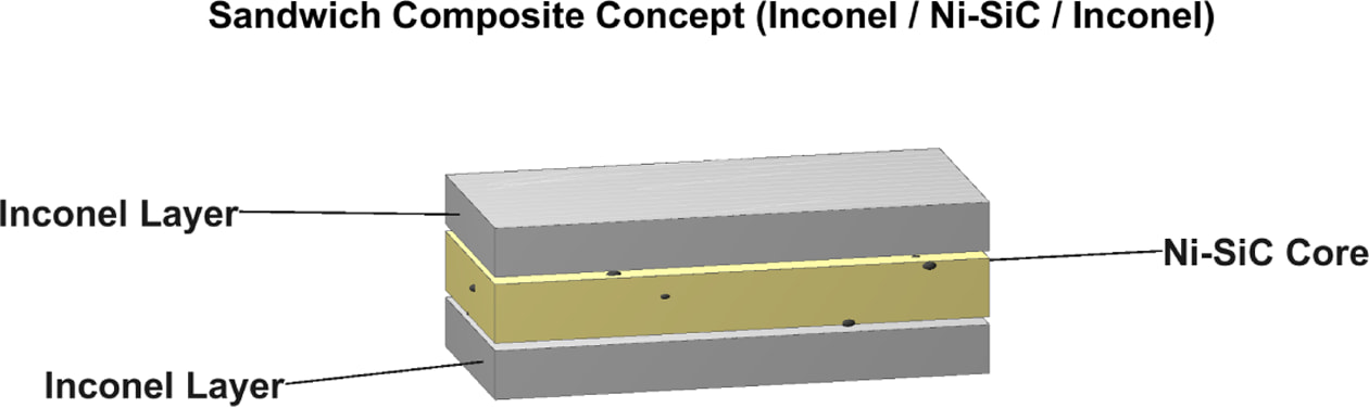
Considering that a complete replacement might cause unacceptable thermal stress and deformation, as shown in Fig. 1, this paper proposes a sandwich structure: Inconel 690 / Ni–SiC / Inconel 690.
The two Inconel 690 layers on either side serve to withstand boundary constraints and provide corrosion resistance and connectivity compatibility; the middle layer uses Ni–SiC metal matrix composite (MMC) to regulate equivalent stiffness, linear expansion, and thermal conductivity, thereby improving the thermal-structural coupling response and reducing the amount of high-cost alloys used.
To reduce the interfacial stress concentration caused by the abrupt change in material properties between the sandwich and outer alloy layers, this paper further considers a discrete gradient sandwich: 0–20–0 vol% SiC. That is, the SiC volume fraction gradually transitions from 0% (pure Ni) at the interface to 20% in the middle layer, and then back to 0% at the other interface along the sandwich thickness direction. This gradient design maintains the sandwich reinforcement effect while allowing the elastic modulus and coefficient of thermal expansion to change more smoothly near the interface, thereby reducing the peak values of interfacial shear stress and normal tensile stress.
2.1.4 Thickness Parametricization
This paper fixes the total wall thickness at 1.5 mm and parametrically scans the interlayer thickness proportions, with interlayer thicknesses accounting for 10%, 20%, and 30% of the total wall thickness. The corresponding total interlayer thicknesses are 0.15 mm, 0.30 mm, and 0.45 mm, respectively; the thicknesses of the two outer Inconel 690 layers under symmetrical conditions are 0.675 mm, 0.600 mm, and 0.525 mm, respectively. For the gradient interlayer (0–20–0), the interlayer is discretized into three equal-thickness sublayers (0%/20%/0%) to achieve layered material application in the finite element method and maintain the same thickness control and comparison scale as the fixed interlayer scheme.
In summary, the parametric design matrix presented in this paper can be summarized as two types of sandwich structures (fixed 20 vol% and 0–20–0 gradient) × three sandwich thickness ratios (10%, 20%, and 30%). Using a full Inconel 690 and a complete replacement scheme as comparisons, the trade-offs between displacement, stress, and heat transfer costs under thermal-structural coupling conditions are systematically evaluated for different structures.
2.2 Geometric and Thickness Parameters
To ensure comparability among different configurations, all models in this study employ identical geometric shapes and overall dimensions; only the material layering scheme and the thickness ratio along the tube wall are varied.
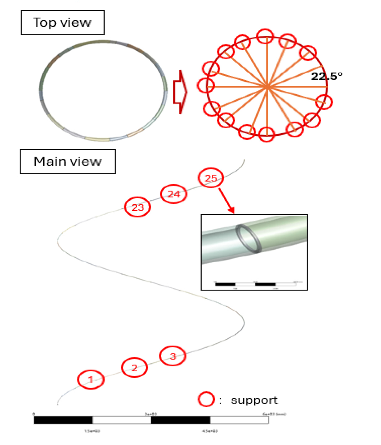
The geometric model was constructed in ANSYS Design Modeler by sweeping an annular cross-section, with an inner diameter of 12 mm and an outer diameter of 15 mm located at a radial distance of 2300 mm from the center, along a helical path with a height of 7000 mm. The number of turns of the heat transfer tube was set to 1.6. The model used in this study is shown in Fig. 2.
2.2.1 Geometric Modeling and Coordinate Definition
A solid spiral tube model is established, and a general coordinate system is used to define the x-axis, y-axis, and z-axis. The heat load is transferred radially through the wall, and the structural response is mainly constrained by the Z-direction constraint. To facilitate subsequent result extraction, the inner and outer surfaces of the tube wall are defined as the inner wall surface and the outer wall surface, respectively, and boundary application areas are defined on the inner and outer surfaces.
2.2.2 Total Wall Thickness and Layering Strategy
The total wall thickness t is used as a uniform control quantity and remains consistent across all schemes. The baseline scheme is a homogeneous single-layer tube wall; the interlayer scheme adopts a sandwich structure, consisting of an outer alloy layer – an intermediate interlayer – an outer alloy layer in the wall thickness direction. To reduce the additional bending effect introduced by geometric asymmetry, this paper assumes a symmetrical distribution of the outer layer thickness on both sides, meaning the outer layer thickness on both sides is equal, and the interlayer is located at the center of the wall thickness.
The interlayer thickness is defined proportionally:

Where tc is the total thickness of the interlayer, and r is the interlayer thickness ratio. This paper selects several representative thickness ratios (such as 10%, 20%, and 30%) for parameterized comparison. Under symmetrical conditions, the thicknesses of the outer layers on both sides are:

2.2.3 Discrete Implementation of Fixed and Gradient Sandwich Layers
In the fixed sandwich layer scheme, the sandwich region is a single material layer (e.g., Ni–SiC with a fixed volume fraction) with a thickness of tc.
In the gradient sandwich layer scheme, to achieve continuous property variation in the finite element method, this paper uses a discretization method to divide the sandwich layer into three layers along the thickness direction, and assigns different SiC volume fractions to each sub-layer to form a symmetrical gradient distribution of 0–20–0. This discretization strategy is easy to implement in conventional finite element software and can also be fairly compared with the fixed sandwich layer scheme while keeping the total sandwich layer thickness tc constant. To reduce degrees of freedom and highlight the main trends, this paper initially uses equal-thickness sub-layer division; the interface stress reduction effect can be further optimized by adjusting the thickness ratio of the intermediate reinforcing layer and the transition layer.
2.2.4 Scheme Naming and Repeatability Description
To facilitate the organization of parametric examples, this paper adopts a naming convention of "structure type – thickness ratio, for example:
• U–r: Fixed interlayer (uniform composition) scheme;
• G–r: Graded interlayer (graded interlayer) scheme;
Where r represents the interlayer thickness ratio. This naming convention helps to uniformly compare the influence of different thicknesses and interlayer forms on temperature field, displacement, and stress indices in the results presentation.
Through the above geometric and thickness parameter definitions, this paper, while maintaining overall dimensional consistency, studies the influence of changes in interlayer thickness ratio and interlayer gradient form on the thermal-structural coupling response and heat transfer cost, thus providing a clear parametric basis for the design choices of interlayer structures.
|
Fig. 1 Conceptual diagram of sandwich structure |
|
Fig. 2 The FEA model of the helical once-through steam generator to be investigated |
3.1 Inconel 690
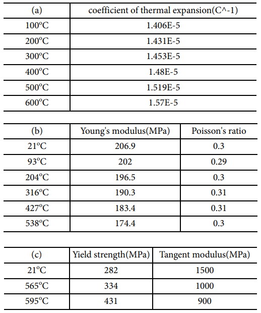
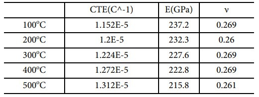
Inconel 690 was used as the reference material for the OTSG heat transfer tube to establish the temperature field, thermal stress, and deformation levels under control conditions. Inconel 690 was treated as an isotropic, continuous homogeneous body, and temperature-dependent material parameters were used in the thermo-structural coupling analysis. Thermophysical and mechanical parameters included: density ρ(T), specific heat C_p(T), thermal conductivity k(T), coefficient of linear expansion α(T), Young's modulus E(T), and Poisson's ratio ν(T). When the structural response might enter the plastic stage, bilinear isotropic hardening (BISO) was used to describe its elastoplastic behavior. The relevant parameters varying with temperature are shown in Table 1 [7,8].
To avoid the mixing of residual stress from the manufacturing process and stress from service conditions, a uniform stress-free reference temperature Tref is set for structural analysis, ensuring that the thermal strain of the material is zero at T=Tref. This paper assumes that Tref is the initial operating temperature of the model (200oC), thus ensuring that the thermal stress mainly reflects the thermal-structural coupling effect caused by changes in operating temperature.
3.2 Ni–SiC MMC
To achieve the design goal of “reducing the amount of expensive alloys and improving the thermal-structural coupling response,” this paper uses Ni–SiC metal matrix composites as sandwich materials, considering two volume fraction combinations:
• Ni–SiC (0 vol%): corresponding to a pure Ni matrix layer, used as a transition layer in gradient sandwiches;
• Ni–SiC (20 vol%): corresponding to a reinforcing layer, used to fix the sandwich or as the central layer in gradient sandwiches.
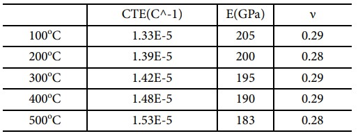
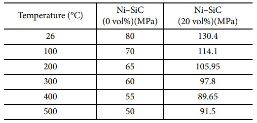
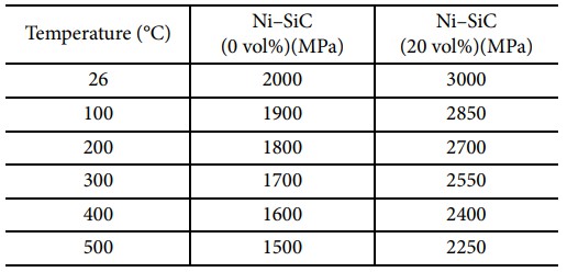
Tables 2 and 3 show the relevant parameters of the two materials as a function of temperature. In the finite element modeling, the Ni–SiC MMC adopts the homogenized isotropic continuum approximation. The purpose of this treatment is to capture the dominant influence of SiC filler on equivalent thermal conductivity, stiffness, and thermal expansion behavior without introducing explicit particle geometry and micro-interface details, while meeting the computational efficiency requirements for parametric comparison.
3.2.1 Definition of Volume Fraction and Density/Specific Heat Mixing Rules
This paper uniformly uses volume fraction Vf to represent the SiC content (vol%), i.e.:

Density is calculated using a linear mixture with volume fraction:

Specific heat is a mass-based physical property, and a mass fraction weighted mixture is used:

The mass fraction wi is obtained by converting the volume fraction and density to ensure equivalence under the principle of energy conservation.
3.2.2 Equivalent Thermal Conductivity (Isotropic)
To match the equivalent description of radial through-wall heat transfer, this paper treats the thermal conductivity of MMC as an isotropic scalar k(T). The equivalent thermal conductivity is constructed using the classical effective medium model [9]:

Where F(·) is a function of volume fraction and thermal conductivity of the two phases. This model reflects the trend that the composite layer's thermal conductivity is enhanced when the filler's thermal conductivity is higher than that of the matrix; and the enhancement effect weakens when the thermal conductivity of the two phases is close or when the filler's thermal conductivity decreases at high temperatures. The model parameters and corresponding temperature values are given in the table in this paper.
3.2.3 Elastic Parameters and Equivalent Thermal Expansion
The equivalent elastic parameters (E, ν) of MMC are estimated using the equivalent method commonly used for particle-reinforced composite materials [10]:

The linear expansion coefficient α(T) is the dominant parameter of thermal strain, and this paper uses an equivalent thermoelastic model for approximation:

The aforementioned equivalent method is used to establish “structural response trends” and “parametric comparisons,” without attempting to precisely reproduce the experimental microscopic mechanisms. Its rationality is verified by comparing the changes in displacement, equivalent stress, and peak interfacial stress under different interlayer thicknesses and gradient forms.
3.2.4 Discrete Implementation of Gradient Layers (0–20–0
To alleviate the interfacial stress concentration caused by abrupt changes in material properties between the interlayer and the outer alloy layer, this paper adopts a discrete gradient strategy. The interlayer is divided into several sub-layers along the thickness direction and each has individually materialized, achieving a symmetrical gradient distribution of 0–20–0 vol%. This discrete gradient allows E, α, and k to change more smoothly near the interface without introducing a complex continuous gradient material model, thereby reducing the peak values of interfacial shear stress and normal tensile stress, and improving structural stability under thermal cycling.
3.3 BISO Parameter Description
To describe the yielding and plastic accumulation effects that may occur under high-temperature thermal loading, this paper uses a bilinear isotropic hardening (BISO) model when necessary. This model approximates the elastoplastic response of a material using a two-stage linear stress-strain relationship:
• Elastic stage: Stress and strain satisfy σ = E(T)ε;
• Post-yield stage: The material enters linear hardening, with the slope being the tangent modulus Et(T).
3.3.1 Yield Strength
Yield strength is defined as the yield point of a material at a given temperature. In the temperature-dependent settings, σy is input separately at each temperature point to reflect the decreasing trend of yield strength at high temperatures. For composite layers (Ni–SiC), if a complete yield database with the same process and temperature is lacking, the reinforcement ratio of the matrix yield strength can be used as an engineering approximation, and the sources of uncertainty are declared in the discussion section. Table 4 shows the yield strength of the two materials as a function of temperature.
3.3.2 Tangent Modulus
The tangent modulus characterizes the hardening slope after yielding and determines the stress-strain growth rate in the plastic zone. Since the tangent modulus is often sensitive to the distribution of residual stress and plastic strain, and direct data in the literature is limited, this paper uses the tangent modulus as a controllable modeling parameter, inputting it at temperature points and performing sensitivity analysis when necessary, to ensure the robustness of the conclusions to the hardening assumption. Table 5 shows the tangent modulus of the two materials as a function of temperature.
4.1 Thermal-Structure Coupled Flowchart
This paper employs a thermal-structure coupled finite element method to evaluate the temperature field, thermal stress, and deformation response of different pipe wall structures under the combined action of thermal and pressure loads. Considering that the temperature field is mainly determined by heat conduction and convection heat transfer, while the structural response is mainly generated by the thermal strain driven by the temperature field superimposed with pressure loads and constraints, the following flowchart is adopted:
1. Thermal Analysis: Solve the transient temperature field T(x,t) under layered material properties and segmented thermal boundary conditions, and output the wall heat flux, internal and external wall temperature difference, etc.
2. Temperature Field Mapping: Map the temperature field obtained from the thermal analysis into the structural analysis model as the input of the structural field temperature load.
3. Structural Analysis: Apply segmented pressure loads and structural constraints on the basis of the temperature load and solve for displacement and stress; consider material elastic-plasticity (BISO) when necessary.
4. Index Extraction and Comparison: Output the maximum displacement, maximum equivalent stress, and Tresca stress after principal stress calculation for comprehensive evaluation
4.2 Thermal Boundaries and Structural Boundaries
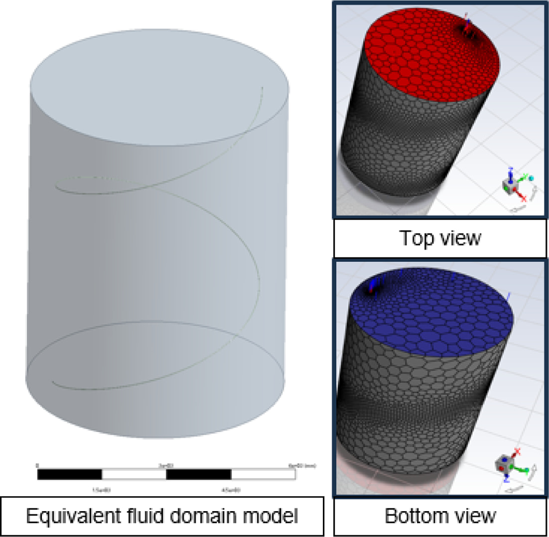
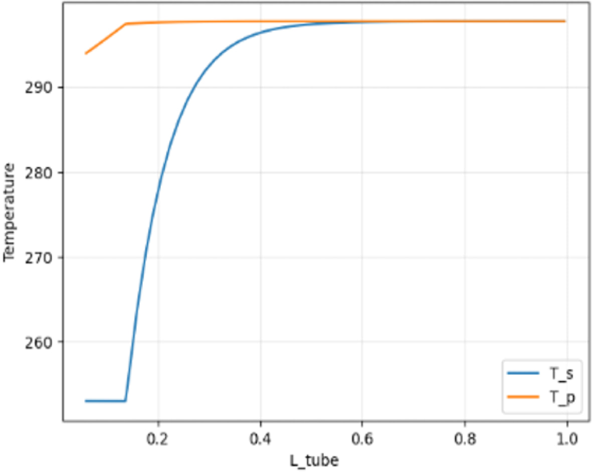
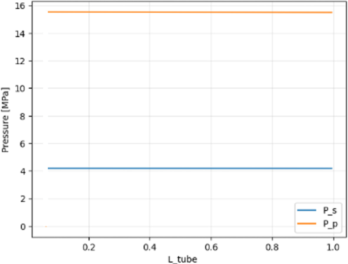
To characterize the axial operating conditions (temperature, pressure) of the OTSG heat transfer tube, this paper divides the boundary settings into 54 continuous segments along the axial direction. Each segment corresponds to an independent set of boundary parameters to achieve segmented load application. An equivalent fluid domain is established, the thermal–fluid field was obtained using ANSYS Fluent to simulate the operating conditions of a once-through steam generator (OTSG). A pressure-based steady-state solver was employed. Turbulence effects were modeled using the realizable k–ε model in conjunction with standard wall functions. The inlet boundary condition was specified as a mass flow inlet with a prescribed temperature, while the outlet boundary condition was defined as a pressure outlet. The interaction between the primary and secondary sides was represented through convective heat transfer across the tube wall. Radiative heat transfer was taken into account using the discrete ordinates (DO) model.A one-way coupling strategy was adopted between the thermal–fluid analysis and the structural analysis. Two representative paths were directly defined along the primary and secondary sides of the heat transfer tube, and the corresponding temperature and pressure distributions along these paths were extracted directly from the simulation results. Figs. 3, 4, and 5 show the equivalent fluid domain, temperature boundary conditions, and pressure boundary conditions, respectively.
This paper uses explicit support modeling: 25 1 mm thick circular rings are arranged axially on the outside of the tube segment as support ends. To avoid over-constraint, only the z-axis displacement constraint is applied to the support rings in the global coordinate system, while the other directions remain free. Fixed constraints are set at the inlet and outlet, thereby allowing radial/circumferential thermal expansion of the tube wall and reducing stress concentration introduced by the boundary conditions. All cases use the same support ring arrangement and constraint form.
4.3 Mesh
This paper uses 3D solid elements to discretize the pipe wall and performs local mesh refinement in the following areas to improve the prediction accuracy of key quantities:
1. Near the layer interface: The peak values of interfacial shear stress and normal stress are sensitive to the mesh and require mesh refinement to reduce numerical errors;
2. Near the segment boundary: Segment temperature/convection parameters or pressure change at the segment boundary, easily causing abrupt gradient changes, requiring appropriate mesh refinement;
3. Near the support: Stress concentration is prone to occur at constraints, and local mesh refinement should be performed.
In the thickness direction, to avoid element conflicts that could “sharpen” abrupt changes in material properties, this paper arranges at least 3 layers of elements in the thickness direction of each material layer; for the discrete sublayers of the gradient sandwich layer, the same is ensured, with at least 2 layers of elements per sublayer.
To ensure the numerical accuracy of the simulation results, a mesh convergence study was conducted. Three levels of mesh density (coarse, medium, and fine) were tested. The coarse mesh contained approximately 0.8 million elements, the medium mesh contained approximately 1.6 million elements, and the fine mesh contained approximately 2.7 million elements. The maximum von Mises stress was used as the evaluation metric. The difference in maximum stress between the medium and fine meshes was found to be less than 3% [11] [12], indicating that the solution is mesh-independent. Therefore, the medium mesh was selected for subsequent simulations to balance computational efficiency and accuracy.
|
Fig. 3 Fluent equivalent fluid domain model |
|
Fig. 4 Temperature Boundary Condition Settings |
|
Fig. 5 Pressure boundary conditions setting |
5.1 Baseline:All 690 vs. All Replacement
In thermo-structural coupling analysis, Von Mises equivalent stress is used as the primary evaluation index for structural response. This is because Von Mises stress can represent a complex three-dimensional stress state as a single scalar value, facilitating a unified assessment of the yield risk of materials under combined thermal and mechanical loads. For ductile metallic materials (such as nickel-based alloys and steel), the Von Mises yield criterion has good applicability and can therefore be used to compare the thermo-structural safety margin under different working conditions, structural designs, or material schemes. This paper evaluates the mechanical reliability of the structure under coupled working conditions by extracting the maximum Von Mises stress from the model. This stress is divided into principal stresses and stress component:
Principal stress form:
When the three principal stresses are known, it can be expressed as:

Stress component form:
In a three-dimensional rectangular coordinate system, when the normal stress and shear stress components are known:

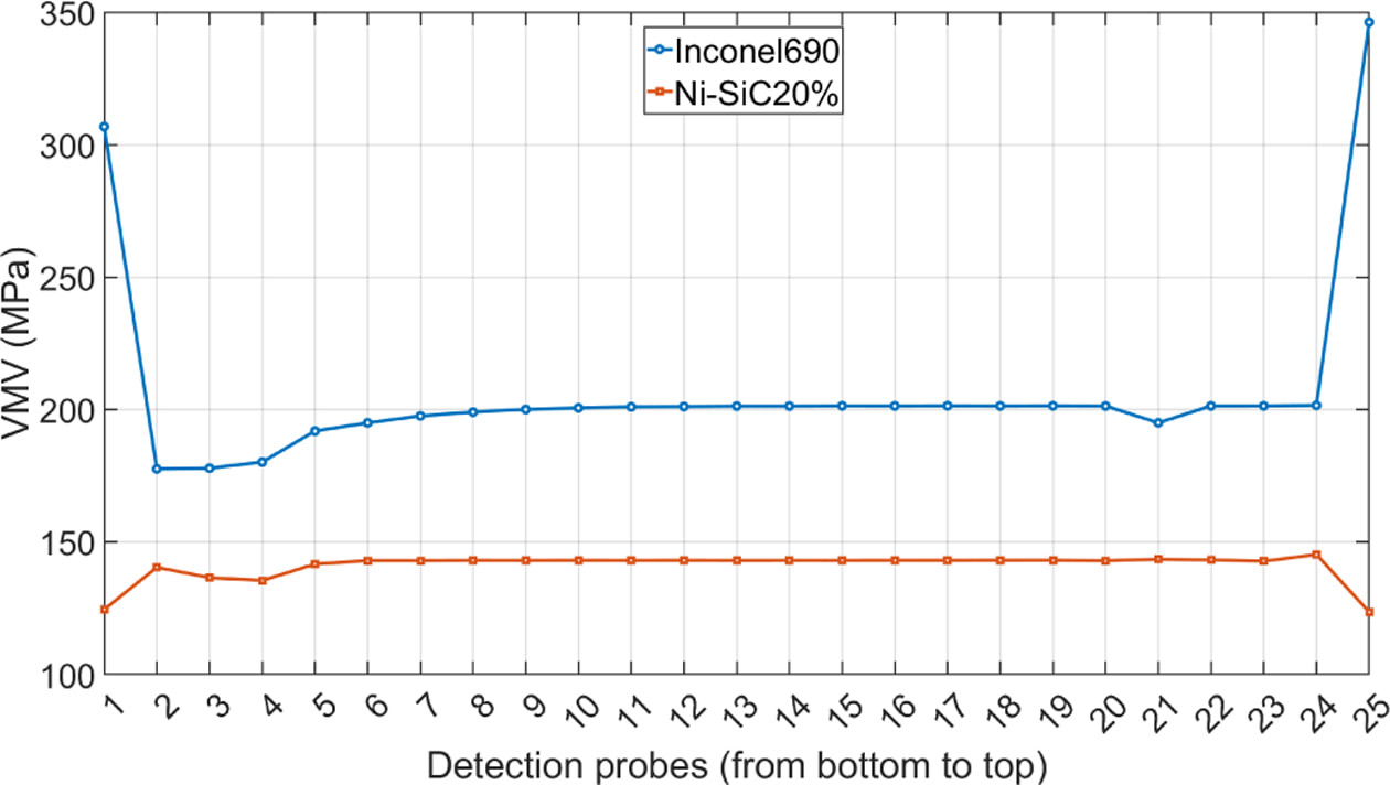
Fig. 6 presents the von Mises equivalent stress distribution at 25 evaluation points (from bottom to top), showing that the full replacement Ni–SiC (20 vol%) configuration achieves a significant reduction in stress compared to the baseline Inconel 690 case. In the central region (points 5–24), the baseline stress remains relatively stable at approximately 195–202 MPa, whereas the replacement scheme exhibits lower values of approximately 142–145 MPa, corresponding to a reduction of about 27–30%. When averaged over all evaluation points, the stress decreases from 207.31 MPa in the baseline case to 140.70 MPa in the replacement case, representing an overall reduction of approximately 32.1%.Notably, the baseline configuration exhibits pronounced stress concentration at the end regions (points 1 and 25), with peak values of 306.78 MPa and 346.25 MPa, respectively. In contrast, the replacement scheme significantly suppresses these end-region stresses to approximately 124.37 MPa and 123.48 MPa, which are not only markedly lower than the baseline peaks but also below the stress levels observed in the central region. This indicates that, under the present segmented thermal–pressure loading and support constraints, the replacement configuration effectively mitigates end-dominated stress concentration, resulting in a more uniform stress distribution. From a thermal perspective, the Ni–SiC composite also exhibits favorable thermal conductivity, suggesting its potential as a heat transfer material. However, despite its superior numerical performance, the feasibility of full replacement cannot be assessed based solely on stress metrics. OTSG heat transfer tubes are multi-objective thermo-mechanical components, requiring consideration of long-term reliability, interfacial stability, fatigue and creep behavior, as well as manufacturability. Therefore, the full replacement scheme is treated here as a reference for numerical comparison and mechanistic analysis, while subsequent sections focus on more practical sandwich and gradient configurations.
5.2 Three-Layer Sandwich
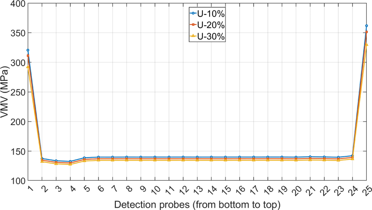
Fig. 7 compares the von Mises equivalent stress distribution at 25 evaluation points for three-layer sandwich structures with fixed interlayer compositions (U-10%, U-20%, and U-30%).
In the central region (points 5–24), all configurations exhibit similar stress levels with only minor variations. In contrast, significant differences are observed at the end regions (points 1 and 25), where stress concentration is most pronounced. Specifically, the U-10% and U-20% configurations show higher peak stresses at the ends compared to the baseline case, whereas the U-30% configuration reduces the end-region peak stress below the baseline level, demonstrating a stronger peak mitigation capability. The increased stress in U-10% and U-20% can be attributed to the combined effects of material mismatch and local constraints introduced by the layered structure. Differences in elastic modulus and coefficient of thermal expansion between the Inconel 690 and Ni–SiC layers generate additional thermal mismatch stresses under thermal loading, while the increased local stiffness limits deformation accommodation, leading to elevated stress levels. These effects are further amplified in the end regions due to segmented thermal–pressure loading and multi-support constraints, where stress concentration is inherently more sensitive. When the interlayer thickness increases to 30%, the interlayer exerts a stronger influence on stress transfer and stiffness distribution, promoting more effective redistribution of thermo-mechanical stresses in the end regions, thereby reducing peak stress below the baseline level. These results indicate that the primary role of fixed interlayer structures is not uniform stress reduction, but redistribution-driven mitigation of localized stress concentration [13]. Their overall effectiveness should therefore be evaluated in conjunction with heat transfer performance, total deformation, and the potential advantages of gradient interlayer designs.
5.3 Gradual Variation
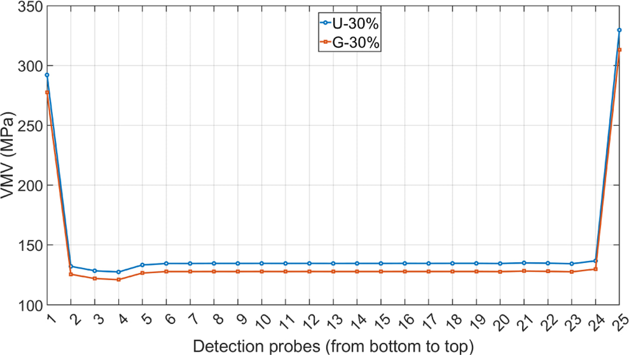
Fig. 8 compares the von Mises equivalent stress distribution at 25 evaluation points for the fixed sandwich (U-30%) and the gradient sandwich (G-30%, 0–20–0 vol%) with an interlayer thickness of 30%.
The results show that the gradient configuration consistently exhibits lower stress levels than the fixed counterpart across nearly all evaluation points, indicating both overall stress reduction and improved distribution uniformity. Specifically, reductions are observed in both end-region peak stresses and the baseline stress levels in the central region. This behavior is primarily attributed to the introduction of a graded transition in material properties—such as elastic modulus, coefficient of thermal expansion, and thermal conductivity—along the thickness direction. Such gradation enables smoother variation of material properties, thereby alleviating thermal mismatch stresses and reducing interface constraint effects associated with abrupt material discontinuities. As a result, stress concentration at end regions and interface-sensitive locations is effectively suppressed. From a thermo-mechanical perspective, the gradient sandwich demonstrates clear advantages in stress mitigation and distribution homogenization, providing a promising direction for structural optimization. However, these benefits come at the cost of increased modeling and computational complexity, due to multi-layer discretization, additional material parameter inputs, and higher mesh requirements. Moreover, practical implementation remains challenging, as manufacturing gradient layers involves precise control of material composition, interface quality, and fabrication processes. Therefore, gradient sandwich structures are better regarded as a conceptual and mechanistic design framework for guiding stress redistribution and peak mitigation, rather than a directly deployable engineering solution at the current stage.
|
Fig. 6 Comparison of VMV stress between full baseline and full replacement |
|
Fig. 7 VMV stress comparison of the three-layer sandwich structure |
|
Fig. 8 Comparison of VMV stress between gradient sandwich layers and fixed composition sandwich layers |
This study investigates the material and structural optimization of heat transfer tubes in i-SMR once-through steam generators (OTSGs) under cost-driven design constraints. A thermo-mechanically coupled finite element framework is developed to evaluate structural responses under segmented temperature and pressure loading, in conjunction with convective heat transfer conditions. With explicit modeling of support constraints, a systematic comparative analysis is conducted among the baseline full Inconel 690 configuration, complete material replacement, and sandwich as well as gradient sandwich structures. The main findings are summarized as follows.
(1) The complete replacement scheme demonstrates a favorable stress response at the numerical level; however, it remains unsuitable for direct engineering implementation. Under identical operating conditions and constraints, the full Ni–SiC (20 vol%) configuration exhibits consistently lower von Mises stress than the baseline Inconel 690 case, with a pronounced reduction in end-region stress concentration. The stress distribution transitions from an “end-dominated peak” pattern to a more uniform profile with slightly elevated mid-span levels. Despite these advantages, OTSG heat transfer tubes are inherently multi-objective thermo-mechanical components, and structural performance cannot be evaluated solely based on a single stress metric. Critical factors, including interfacial stability, fatigue and creep resistance, and manufacturability under long-term high-temperature service conditions, remain insufficiently validated for Ni–SiC materials. Therefore, the complete replacement scheme is regarded in this study as a reference for numerical comparison and mechanistic interpretation, rather than a viable option for immediate engineering application.
(2) Three-layer sandwich structures enable effective stress redistribution and local peak mitigation at the structural level. By employing an Inconel 690 / Ni–SiC MMC / Inconel 690 configuration, the outer alloy layers preserve corrosion resistance and structural compatibility, while the intermediate layer provides tunable stiffness, thermal expansion, and thermal conductivity. As a result, the stress field can be actively reconfigured. Numerical results indicate that the primary role of the sandwich architecture is not global stress reduction, but rather the attenuation of localized peak stresses—particularly at end regions—through redistribution mechanisms, thereby improving the overall structural response under coupled thermo-mechanical conditions.
(3) A clear trade-off exists between interlayer thickness, peak stress mitigation, and heat transfer performance. As the interlayer thickness increases from 10% to 30%, the structural response exhibits a pronounced nonlinear trend. Under certain operating conditions, the U-10% and U-20% configurations show elevated end-region stresses exceeding the baseline level, primarily due to enhanced thermal mismatch (differences in elastic modulus and coefficient of thermal expansion) coupled with local constraint effects. When the interlayer thickness reaches 30%, the increased influence of the interlayer on stress transmission and stiffness distribution enables more effective redistribution of thermo-mechanical stresses, leading to a reduction in end-region peak stress below the baseline level. However, increasing interlayer thickness also alters the through-wall temperature gradient (or equivalently, the thermal resistance), indicating that interlayer thickness is not a monotonically optimal parameter. Instead, an optimal design requires balancing stress mitigation against heat transfer efficiency.
(4) Gradient interlayers (0–20–0 vol%) further enhance stress reduction and improve stress distribution uniformity. Compared with fixed interlayer configurations (e.g., U-30%), the graded interlayer (G-30%) consistently exhibits lower von Mises stress across nearly all evaluation points, indicating both overall stress reduction and effective local peak mitigation. This improvement is primarily attributed to the introduction of a transitional material gradient, which enables smoother variation of key material properties—namely elastic modulus, coefficient of thermal expansion, and thermal conductivity—along the thickness direction. As a result, thermal mismatch stresses and interface constraint effects associated with abrupt material discontinuities are significantly alleviated, thereby reducing stress concentration risks at end regions and interface-sensitive locations.
(5) The proposed numerical framework provides a practical basis for structural scheme selection and parameter optimization. By employing maximum displacement, maximum equivalent stress, and peak Tresca (or von Mises) stress as evaluation metrics, a reproducible parametric comparison methodology is established, enabling quantitative assessment of different interlayer configurations. The results indicate that interlayer thickness ratio and gradient design can be systematically optimized within this framework. Considering the combined effects of structural response, stress distribution uniformity, and heat transfer performance, a moderate interlayer thickness generally achieves a more balanced overall performance, while gradient interlayer designs offer an effective pathway for further peak stress mitigation.
(6) Limitations and Future Work: The present study adopts equivalent isotropic material models and simplified constitutive assumptions (such as the BISO model) for engineering-level analysis. Microstructural effects, interfacial damage, diffusion, creep, and fatigue behavior are not explicitly considered. In addition, the homogenization of Ni–SiC metal matrix composites neglects local particle distribution and interface interactions. Therefore, the results of this study should be interpreted as a comparative and conceptual evaluation of structural trends rather than a fully predictive engineering design tool. Future work will incorporate experimental validation, more detailed interface modeling, and long-term performance assessment under thermal cycling conditions.
This work was supported by Technology Innovation Program (or Industrial Strategic Technology Development Program, 20026462) funded by the Ministry of Trade, Industry and Energy (MOTIE, Korea).
- 1. Harrod, “Alloy optimization for PWR steam generator heat-transfer tubing,” JOM, Vol. 53, No. 7, 2001, pp. 14-17.
-

- 2. Pei, W., Eckert, J., Prashanth, K.-G., Wu, M.W., Kaban, I., Xi, L.-X., and Scudino, S., “A comprehensive review of aluminium matrix composite reinforcement and fabrication methodologies,” Functional Composites and Structures, Vol. 30, No. 8, 2021, pp. 2001–2034.
-
- 3. Li, W., Liu, J., Wang, C., Wang, B., Qiu, S., Su, G.H., and Tian, W., “Three-dimensional thermal–mechanical analysis of helical coil once-through steam generator,” Applied Thermal Engineering, Vol. 263, 2025.
- 4. Jeong, K., Jeong, J.Y., Nam, H.S., Roh, H.D., Ahn, K., and Yoon, J., “Numerical analysis of residual stress in the bending process using kinematic isotropic hardening models for a helical tube in SMR and a U-bent tube in PWR,” Nuclear Engineering and Technology, Vol. 57, No. 10, 2025, 103737.
-
- 5. Srinivas, P.N.S., Babu, P.R., and Balakrishna, B., “Material characterization and optimization of CNT-reinforced aluminum (AA7075) functionally graded material processed by ultrasonic cavitation,” Functional Composites and Structures, Vol. 2, No. 4, 2020, 045002.
-
- 6. Dai, T., Li, B., Tao, C., He, Z.-Z., and Huang, J., “Thermo-mechanical analysis of a multilayer hollow cylindrical thermal protection structure with functionally graded ultrahigh-temperature ceramic to be heat resistant layer,” Aerospace Science and Technology, Vol. 124, 2022, 107532.
- 7. Special Metals Corporation, INCONEL¢ç alloy 690 datasheet.
-
- 8. ASME Boiler and Pressure Vessel Code, Section II: Materials, Part D: Properties (Metric), ASME BPVC.II.D.M-2025, ASME, 2025.
- 9. Sevostianov, I., Mogilevskaya, S.G., and Kushch, V.I., “Maxwell’s methodology of estimating effective properties: Alive and well,” International Journal of Engineering Science, Vol. 140, 2019, pp. 35–88.
- 10. Schapery, R., “Thermal Expansion Coefficients of Composite Materials Based on Energy Principles,” Journal of Composite Materials, Vol. 2, No. 3, 1968, pp.380-404.
-
- 11. Versteeg, H.K., and Malalasekera, W., An Introduction to Computational Fluid Dynamics: The Finite Volume Method, 2nd ed., Pearson Education Limited, 2007.
- 12. Roache, P.J., Verification and Validation in Computational Science and Engineering. Hermosa Publishers, 1998.
- 13. Birman, V., and Byrd, L.W., “Modeling and analysis of functionally graded materials and structures,” Applied Mechanics Reviews, Vol. 60, 2007, pp. 195–216.
 This Article
-
2026; 39(3): 218-227
Published on Jun 29, 2026
- 10.7234/composres.2026.39.3.218
- Received on Mar 1, 2026
- Revised on Mar 29, 2026
- Accepted on May 9, 2026
Services
- Abstract
1. introduction
2. structural design and research scheme
3. material model and parameters
4. numerical methods and boundary conditions
5. results discussion
6. conclusions
- Acknowledgements
- References
- Full Text PDF
Shared
Correspondence to
- Sang-Ha Hwang* , Hyung Doh Roh**
-
* Department of Mechanical Engineering, Hanyang University ERICA, these authors contributed equally to this work.
** Materials Science and Chemical Engineering Center, Institute for Advanced Engineering (IAE) - E-mail: hwang113@iae.re.kr, rhd1213@hanyang.ac.kr
 Copyright ⓒ The Korean Society for Composite Materials. All rights reserved.
Gangnam Mirae Tower, Suite 601, 174 Saimdang-ro, Seocho-gu, Seoul 06627, South Korea
Tel: +82-2-598-1550 Fax: +82-2-598-1557 E-mail: composites@kscm.re.kr